Axial ultrasonic vibration hydraulic bulging structure for tubular product

A technology of hydraulic bulging and ultrasonic vibration, applied in metal processing equipment, forming tools, manufacturing tools, etc., can solve problems such as complex structure, inconvenient operation, and increased risk of wrinkles

Pending Publication Date: 2020-02-11
GUILIN UNIV OF ELECTRONIC TECH
View PDF2 Cites 1 Cited by
  • Summary
  • Abstract
  • Description
  • Claims
  • Application Information

AI Technical Summary

Problems solved by technology

At present, there are mainly two kinds of common pipe axial bulging structures, one is "external control liquid filling pressurized type", for example, Chinese patent ZL00208694.8 discloses an internal high pressure forming machine, and the special external liquid supply system is The pipe provides hydraulic pressure, and at the same time configures a press to apply axial pressure to the pipe, and realizes the axial bulge of the pipe by reasonably matching the hydraulic pressure and the axial displacement of the pressure head of the press. The axial pressure of the device promotes the expansion of the pipe. The material feeding in the forming area improves the forming performance of the pipe, but two independent systems are used to control the forming process of the pipe, the structure is complex, the operation is inconvenient, the cost is extremely high, and a fast replenishment speed is required, which increases the risk of wrinkles
The other is the "internal fluid replenishment pressurized type". For example, Chinese patent ZL200820104296.1 discloses a hydraulic bulging device for pipes, which squeezes the liquid in the pressurized rigid body through the booster piston without the need for an external liquid supply system. Provide the hydraulic pressure required for forming the pipe, and at the same time, the booster piston pushes the hollow pressure head located on the lower body of the booster cylinder to provide the axial force for the pipe. The structure of the device is simple, the liquid replenishment speed is fast, no external hydraulic supply system is required, the o

Method used


Image

  • Axial ultrasonic vibration hydraulic bulging structure for tubular product
  • Axial ultrasonic vibration hydraulic bulging structure for tubular product
  • Axial ultrasonic vibration hydraulic bulging structure for tubular product

Examples


Embodiment

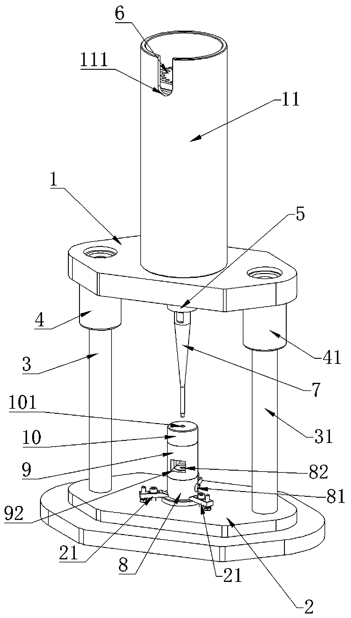
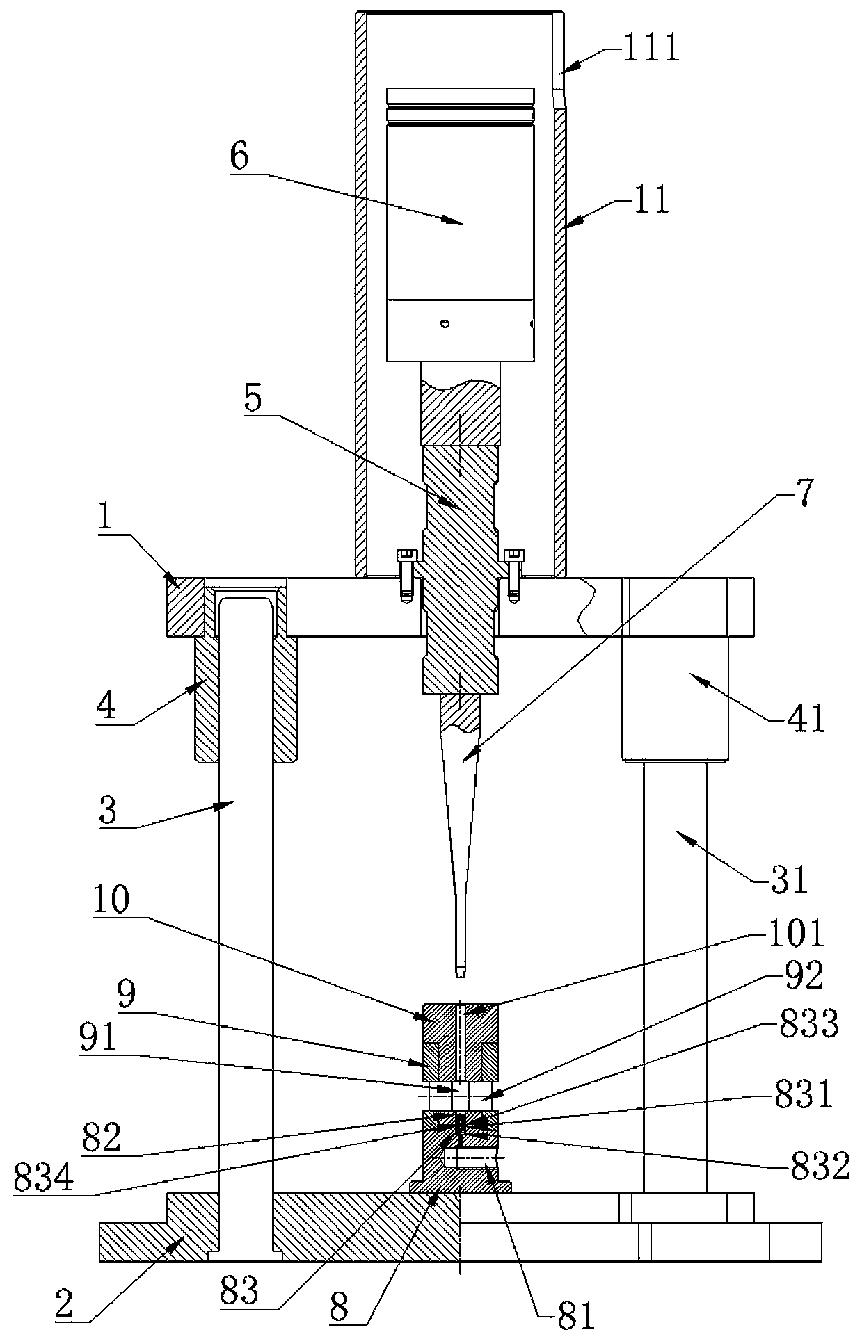
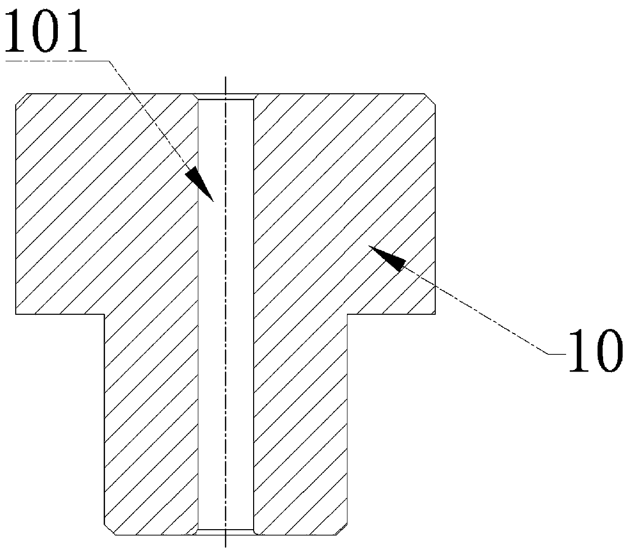
[0023] refer to figure 1 , figure 2 , a pipe axial ultrasonic vibration hydraulic bulging structure, including upper die base 1 and lower die base 2 arranged in parallel up and down, between the upper die base 1 and the lower die base 2 is provided with a first guide post 3 and a second guide Column 31, the upper die base 1 is provided with the first guide sleeve 4 and the second guide sleeve 41 which are respectively fitted with the first guide post 3 and the second guide post 31, and the upper die base 1 is provided with a Horn 5, the upper end of the horn 5 is provided with a transducer 6, the lower end is provided with a shaft pressure head 7, the transducer 6 is equipped with an ultrasonic generator connected, and the upper surface of the lower mold base 2 is from bottom to bottom. A liquid-filled base 8, a spacer ring 9 and a positioning ring 10 are arranged in sequence on the top, and the axis of the positioning ring 10 is located directly below the lower end of the a...


PUM


Abstract

The invention discloses an axial ultrasonic vibration hydraulic bulging structure for a tubular product. The axial ultrasonic vibration hydraulic bulging structure for the tubular product comprises anupper die base and a lower die base which are arranged in parallel up and down, wherein a first guide column and a second guide column are arranged between the upper die base and the lower die base;the upper die base is provided with a first guide sleeve and a second guide sleeve which are arranged on the first guide column and the second guide column in a sleeving manner correspondingly; the upper die base is provided with an amplitude-change pole penetrating the upper die base; an energy converter is arranged at the end of the upper end of the amplitude-change pole, and a shaft pressing head is arranged at the end of the lower end of the amplitude-change pole; and a liquid filling base, a distance ring and a positioning ring are sequentially arranged on the upper surface of the lower die base from bottom to top. The axial ultrasonic vibration hydraulic bulging structure for the tubular product is simple in structure, convenient to dismount and mount, easy to operate, high in tubular product forming efficiency and low in needed shaft pressure and hydraulic pressure, the bulging length of a tubular product can be adjusted, and bulging of a special-shaped section pipe fitting is achieved.

Description

technical field [0001] The invention relates to ultrasonic vibration assisted pipe hydroforming equipment, in particular to a pipe axial ultrasonic vibration hydraulic bulging structure. Background technique [0002] Ultrasonic vibration pipe hydroforming technology is based on the pipe hydroforming technology, using the high-frequency vibration of the ultrasonic vibration device to improve the forming environment of the pipe hydraulic bulging, and improve the new technology of pipe forming performance. At present, there are mainly two kinds of common pipe axial bulging structures, one is "external control liquid filling pressurized type", for example, Chinese patent ZL00208694.8 discloses an internal high pressure forming machine, and the special external liquid supply system is The pipe provides hydraulic pressure, and at the same time configures a press to apply axial pressure to the pipe, and realizes the axial bulge of the pipe by reasonably matching the hydraulic press...

Claims


Application Information

Patent Timeline
IPC IPC(8): B21D26/047B21D26/035B21D37/14
CPCB21D26/035B21D26/047B21D37/14
Inventor 杨连发陈占斌黄一晋黄进杰宗鹏举
Owner GUILIN UNIV OF ELECTRONIC TECH
Why Eureka
Try Eureka