M-BUS host transmit-receive circuit

A technology of M-BUS, transceiver circuit, applied in the field of M-BUS host transceiver circuit, can solve the problems of reducing the maximum value of the power supply current of the loaded equipment, low sensitivity of the receiving circuit, and large resistance value of the resistance, so as to improve the receiving sensitivity, Sampling resistor avoids and improves the effect of sending current

Pending Publication Date: 2020-02-11
QINGDAO EASTSOFT COMM TECH
View PDF0 Cites 2 Cited by
  • Summary
  • Abstract
  • Description
  • Claims
  • Application Information

AI Technical Summary

Problems solved by technology

[0005] 1) The resistance value of the sampling resistor is relatively large, which reduces the maximum value of the power supply current of the load-carrying device
[0006] 2) The average value comparator of the receiving circuit is prone to saturation, especially when the baud rate is low and 0 is continuously sent
[0008] 4) The sensitivity of the receiving circuit is low. To improve the sensitivity, it is necessary to increase the value of the sampling resistance and reduce the maximum value of the power supply current of the load-carrying device.

Method used


Image

  • M-BUS host transmit-receive circuit
  • M-BUS host transmit-receive circuit
  • M-BUS host transmit-receive circuit

Examples


Embodiment Construction

[0030] In order to make the technical solutions and advantages of the present invention clearer, the technical solutions of the present invention will be clearly and completely described below in conjunction with specific embodiments and accompanying drawings. Obviously, the described embodiments are part of the embodiments of the present invention, and Not all of the embodiments; based on the embodiments of the present invention, all other embodiments obtained by those of ordinary skill in the art without creative efforts fall within the protection scope of the present invention.

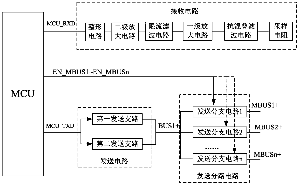
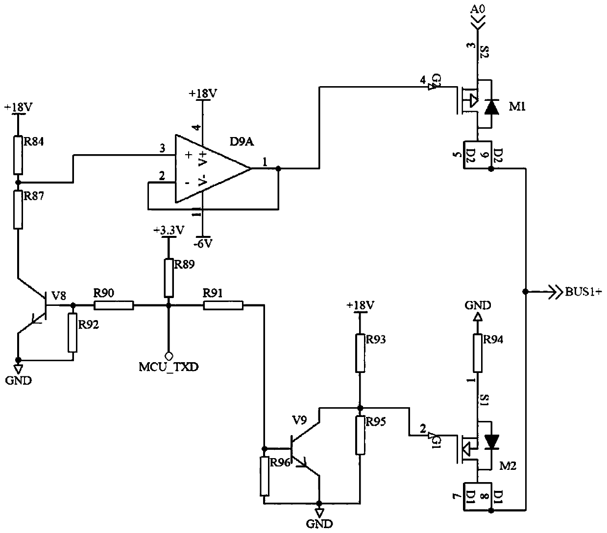
[0031] Such as figure 1 As shown, the embodiment of the present invention provides an M-BUS host transceiver circuit, including a receiving circuit, a transmitting circuit, a transmitting branch circuit and a current limiting circuit.

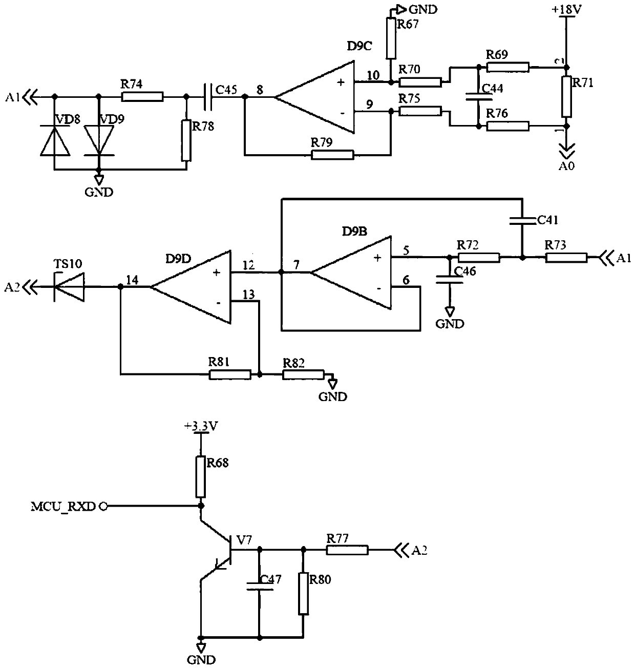
[0032]Wherein, the receiving circuit includes a sampling resistor R71, an anti-aliasing filter circuit, a primary amplifier circuit, a current-limiting filter circu...


PUM


Abstract

The invention belongs to the field of communication and electronic circuits, and provides an M-BUS host transceiver circuit, which comprises a receiving circuit, a transmitting circuit, a transmittingshunt circuit and a current limiting circuit, in the receiving circuit, after a current signal sent by a slave is sampled by a sampling resistor, the sampled signal passes through an anti-aliasing filter circuit, a first-stage amplification circuit, a current-limiting filter circuit, a second-stage amplification circuit and a shaping circuit in sequence and then is input into an MCU; in the transmitting circuit, a control signal is divided into two paths after entering the circuit, one path controls the on or off of a PMOS transistor through an amplifier controlled by a triode, and the otherpath controls the on or off of an NMOS transistor through a triode. The transmitting shunt circuit comprises a plurality of transmitting branches, each transmitting branch is provided with an MOS tube, the MOS tubes are controlled through gating signals of the single-chip microcomputer to achieve opening of a signal path, and the current limiting circuit is used for limiting current of the transmitting shunt circuit. The current transmitting and receiving sensitivity is improved, and the method can be widely applied to the field of communication.

Description

technical field [0001] The invention relates to the technical field of communication and electronic circuits, in particular to an M-BUS host transceiver circuit. Background technique [0002] At present, the M-BUS bus is widely used in the automatic meter reading system of public utility meters such as water, gas and heat meters, and can also be used in various industrial control systems. It is an excellent bus protocol for one-to-many communication. It has the characteristics of strong anti-interference ability, simple circuit structure of the slave machine, self-power supply of the bus master, no need to distinguish the polarity of the slave machine, and is very suitable for public utility metering systems. [0003] The bus transmits signals through current or voltage, the master transmits data to the slave by changing the bus voltage, and the slave responds to the master by changing the load current. The circuit design is divided into sending circuit and receiving circu...

Claims


Application Information

Patent Timeline
Patent Type & Authority Applications(China)
IPC IPC(8): H04B1/10H04B1/40
CPCH04B1/10H04B1/40
Inventor 崔健董海涛王宪贤姜宇果
Owner QINGDAO EASTSOFT COMM TECH
Why Eureka
Try Eureka