[0018] The technical solutions in the embodiments of the present invention will be clearly and completely described below in conjunction with the accompanying drawings in the embodiments of the present invention. Obviously, the described embodiments are only a part of the embodiments of the present invention, rather than all the embodiments. Based on the embodiments of the present invention, all other embodiments obtained by those of ordinary skill in the art without creative work shall fall within the protection scope of the present invention.
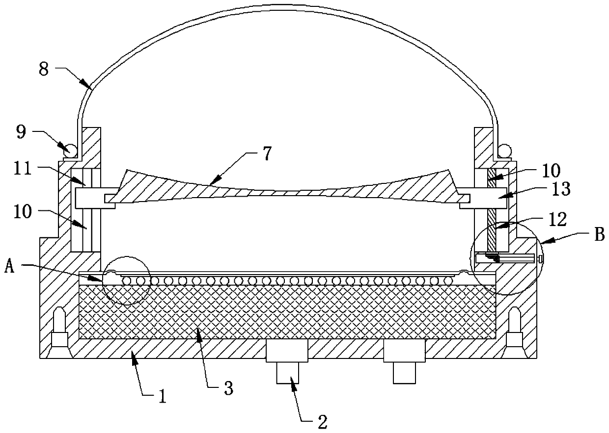
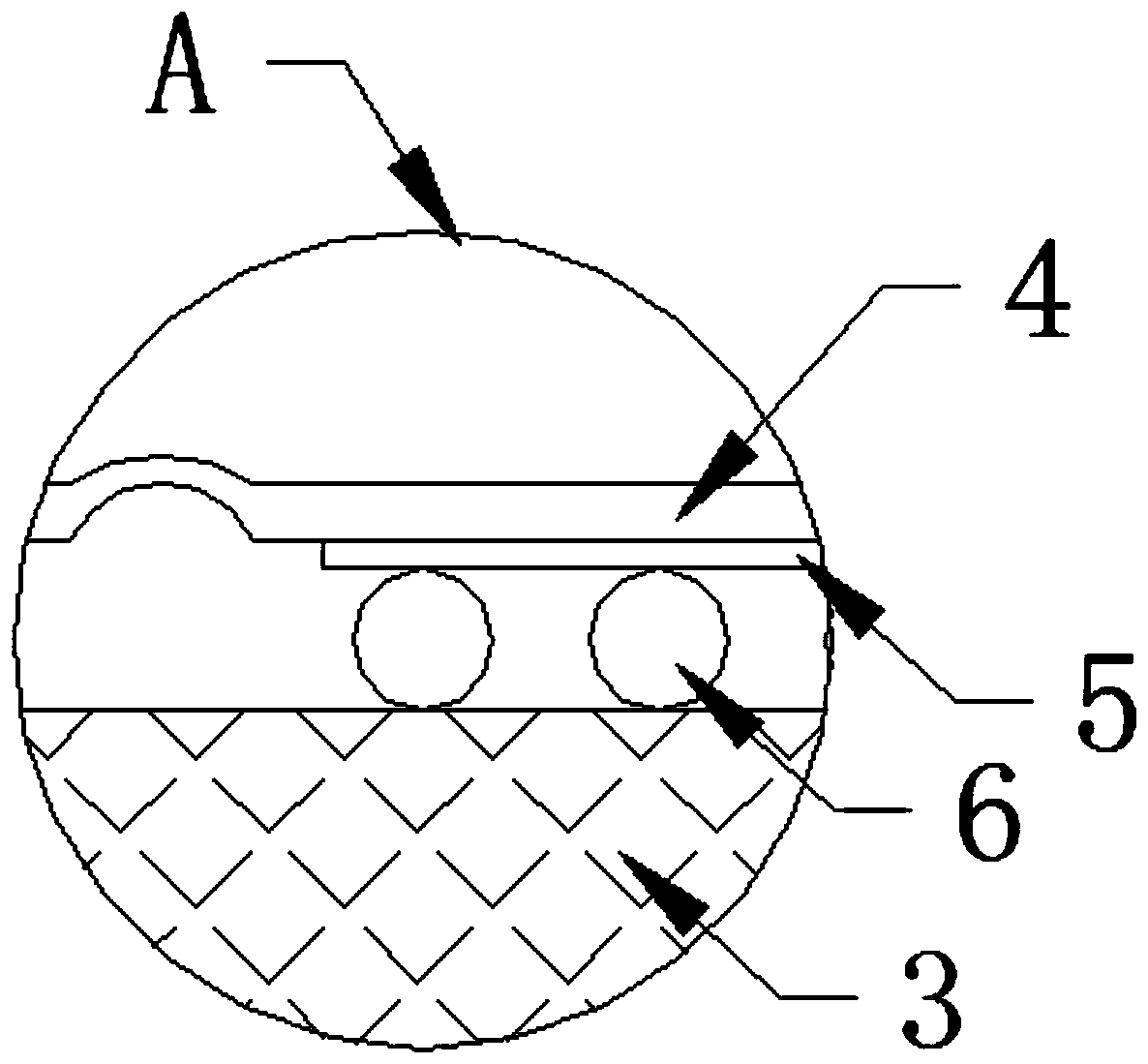
[0019] See Figure 1-3 , The present invention provides a technical solution: a shock wave source structure for a shock wave therapy machine, comprising a housing 1 and a high-voltage connector 2 installed at the bottom of the housing 1. A ceramic base 3 and a ceramic base 3 are installed at the bottom of the inner cavity of the housing 1. There is a coil 6 on the upper part of the, the ceramic base 3 and the coil 6 form an electro-magnetic disk, a rubber membrane 4 is provided above the ceramic base 3, and a metal diaphragm 5 is provided at the bottom of the rubber membrane 4. The electro-magnetic disk is under the action of high-voltage pulse current , Forming a strong magnetic field, the metal diaphragm 5 pushes the water molecules to move to form a plane shock wave, the rubber diaphragm 4 is used for sealing to prevent water from entering the lower layer, the top of the housing 1 is connected to the water bag 8 through the water bag hoop 9 and the inner cavity of the housing 1 A lens 7 is arranged above the rubber membrane 4. The plane shock wave generated by the above is focused by the lens 7. The lens 7 is embedded in the connecting frame 13. During treatment, the water bag 8 of the shock wave source contacts the patient's skin, and the super wave Disperse into the human body through the water bladder 8 and focus on the stones to break the stones.
[0020] The inner wall of the housing 1 is provided with a ring groove 10, one side of the ring groove 10 is vertically installed with a guide post 11, the other side of the ring groove 10 is vertically installed with a screw rod 12, and the connecting frame 13 is sleeved on the guide post 11 and the wire. On the rod 12, a gear groove 14 is opened in the housing 1 and below the screw rod 12. The bottom end of the screw rod 12 extends to the bottom end of the gear groove 14 and a driven helical gear 15 is provided. The movable helical gear 15 is provided with a connecting shaft 16, one end of the connecting shaft 16 is provided with a driving helical gear 19 meshing with the driven helical gear 15, the other end of the connecting shaft 16 extends to the outside of the housing 1, and the connecting shaft 16 is manually aligned It rotates, thereby driving the driving helical gear 19 and the driven helical gear 15 to engage, thereby driving the screw 12 to rotate. The connection relationship between the screw 12, the guide column 13 and the connecting frame 13 can drive the connecting frame 13 The lens moves up and down to realize the adjustment of the focus position.
[0021] Wherein, the connection between the connecting shaft 16 and the housing 1 is provided with a sealed bearing, and the gear groove 14 is sealed by the sealed bearing to prevent external dust from entering the gear groove 14, and under the action of the sealed bearing, the connecting shaft 16 can be stabilized Spin.
[0022] Wherein, one end of the connecting frame 13 is provided with a through hole adapted to the guide post 11, and the other end of the connecting frame 13 is provided with a screw hole for screw connection with the screw rod 12, through the screw 12, the guide post 13 and the connecting frame The connection relationship of 13 can drive the lens located on the connection frame 13 to move up and down, thereby realizing the adjustment of the focus position.
[0023] Wherein, a section of the screw rod 12 penetrating the ring groove 10 and the gear groove 14 is connected by a bearing 18. The bearing 18 can be a sealed bearing, which can ensure the rotation of the screw rod 12 and seal the gear groove 14 and the ring groove 10 at the same time.
[0024] Wherein, the other end of the connecting shaft 16 extends to the outside of the housing 1 with a knob 17 provided with anti-skid patterns. When the focus position needs to be adjusted, the knob 17 is manually rotated to drive the connecting shaft 16 to rotate.
[0025] The specific working principle is as follows:
[0026] When in use, the external power is connected to the high-voltage connector 2 under the casing 1, so that under the action of the electro-magnetic disk composed of the ceramic base 3 and the coil 6 and the metal diaphragm 5, the disk-shaped coil 6 forms a powerful under the action of the high-voltage pulse current The magnetic field pushes the metal diaphragm 5 to press the water molecules to move to form a plane shock wave, which is then focused by the lens 7. The shock wave source water bladder 8 contacts the patient's skin, and the super wave is dispersed into the human body through the water bladder 8 and focused on the stone to break the stone .
[0027] When the focal position of the lens 7 needs to be adjusted, it is only necessary to rotate the external knob 17, under the action of the connecting shaft 16, the driving helical gear 19 and the driven helical gear 15, to drive the screw 12 to rotate, and the connecting frame 13 There is a through hole adapted to the guide post 11 at one end, and the other end of the connecting frame 13 has a screw hole for screw connection with the screw rod 12. Through the connection relationship of the screw rod 12, the guide post 11 and the connecting frame 13, The lens on the connecting frame 13 can be driven to move up and down, so as to realize the adjustment of the focus position, realize the change of the focus position, and can perform long-distance treatment well. The structure is simple and easy to use.
[0028] In the description of this specification, the description with reference to the terms "one embodiment", "example", "specific example", etc. means that the specific feature, structure, material or characteristic described in combination with the embodiment or example is included in at least the present invention. In one embodiment or example. In this specification, the schematic representations of the above terms do not necessarily refer to the same embodiment or example. Moreover, the described specific features, structures, materials or characteristics may be combined in any one or more embodiments or examples in a suitable manner.
[0029] The preferred embodiments of the present invention disclosed above are only used to help explain the present invention. The preferred embodiment does not describe all the details in detail, nor does it limit the invention to only the described specific embodiments. Obviously, many modifications and changes can be made according to the content of this manual. This specification selects and specifically describes these embodiments in order to better explain the principles and practical applications of the present invention, so that those skilled in the art can understand and use the present invention well. The present invention is only limited by the claims and their full scope and equivalents.