Production device for dry-mixed mortar

A production device and a technology for dry powder mortar, which are applied to unloading devices, clay preparation devices, and clay mixing devices, etc., can solve the problems of pipeline impact and wear, reduced equipment durability, and reduced production efficiency, so as to improve work efficiency and avoid problems. The effect of reduced service life and convenient operation

Pending Publication Date: 2020-02-14
开封市筑帮商品砂浆有限公司
View PDF0 Cites 2 Cited by
  • Summary
  • Abstract
  • Description
  • Claims
  • Application Information

AI Technical Summary

Problems solved by technology

[0003] However, the current various solid components are usually conveyed by the pipeline through the screw or the gravity of the material itself. Although the gravity of the material itself is used to transport in the pipeline, although the corresponding power device is saved, the solid component usually has a large impact on the pipeline. The wear is more serious, especially the corners of the pipeline are impacted and worn by high-velocity solid materials for a long time, the durability of the equipment is greatly reduced, and it is often necessary to stop production for maintenance, resulting in a greatly reduced production efficiency

Method used


Image

  • Production device for dry-mixed mortar
  • Production device for dry-mixed mortar
  • Production device for dry-mixed mortar

Examples


Embodiment 1

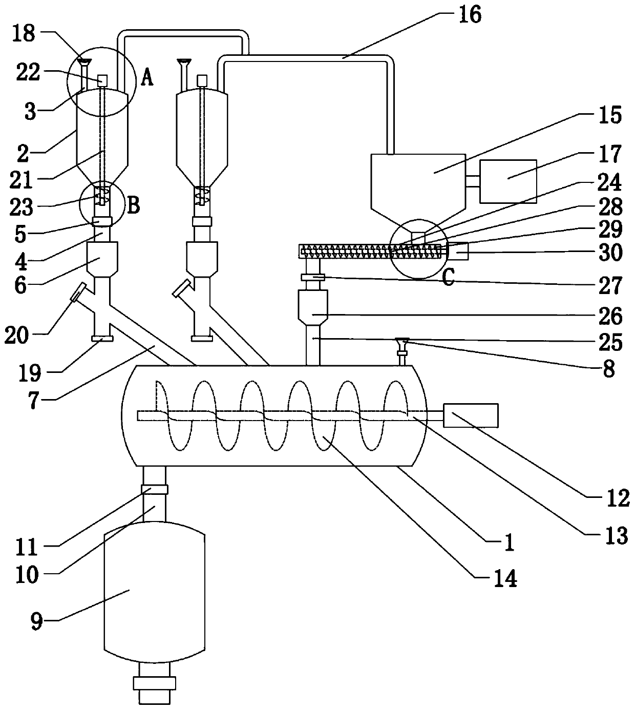
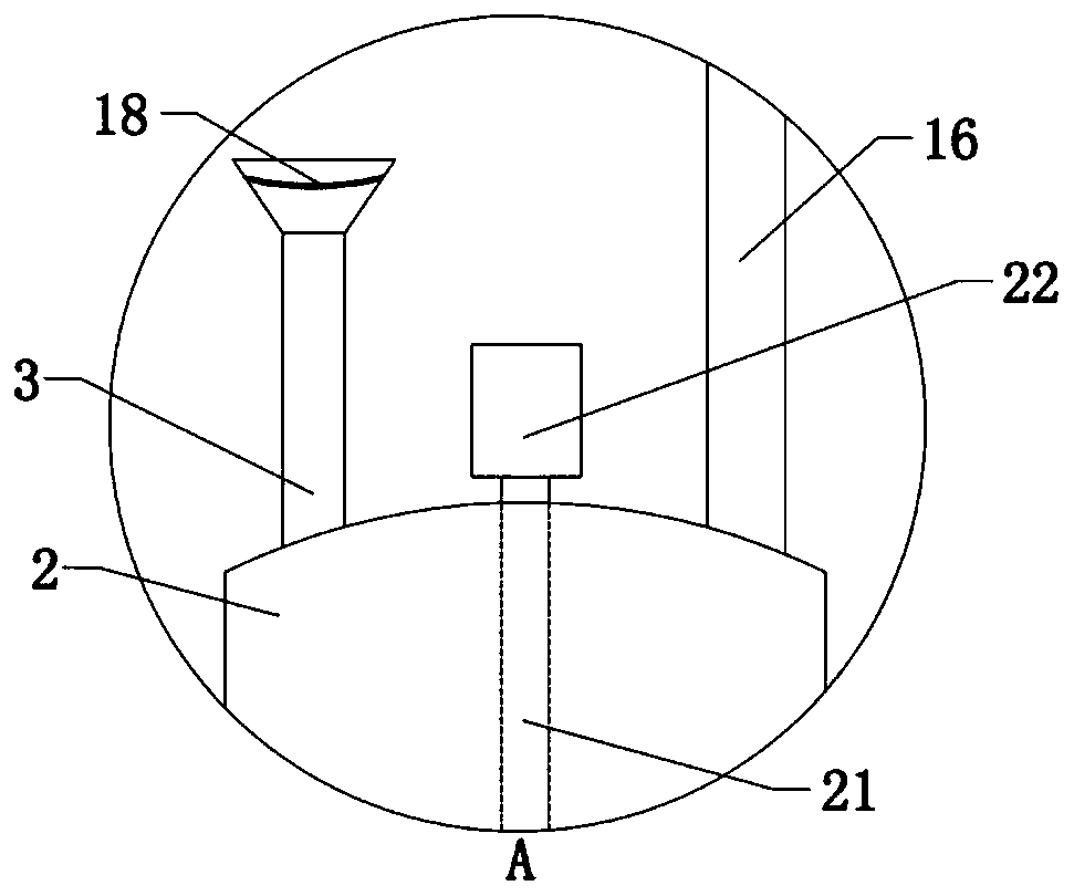
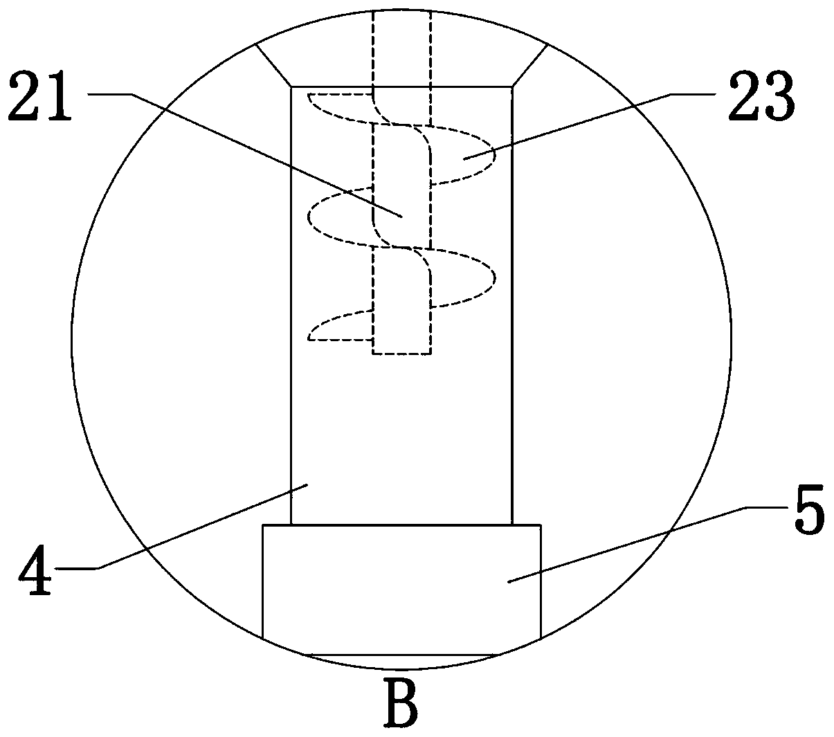
[0032] Embodiment 1: as figure 1 , 2 , 3, and 4, first, add solid raw materials to the raw material tank 2 through the feeding pipe 3, and when the solid raw materials pass through the sieve plate 18 on the feeding pipe 3, large debris cannot pass through the sieve plate 18 and stay above the sieve plate 18 After the solid raw material is added, the first pneumatic butterfly valve 5 is opened, and the raw material conveying motor 22 is turned on at the same time. The raw material conveying motor 22 drives the raw material conveying screw blade 23 to rotate by driving the raw material conveying shaft 21 to control the flow rate of the solid raw material. The raw material enters the raw material weighing tank 6 through the first raw material delivery pipe 4 to be weighed. When the preset standard is reached, the first pneumatic butterfly valve 5 is closed and the raw material delivery motor 22 is turned off at the same time, and then the bottom of the solid raw material weighing...

Embodiment 2

[0036] Embodiment 2: as Figure 5 , 6 , 7, and 8, compared to Embodiment 1, the mixing tank 1 of this embodiment adopts a closed cylindrical box-shaped structure composed of a fixed part and a movable part, and a temporary storage warehouse for finished products is arranged below the mixing tank 1 31. In the stirring state, the fixed part and the movable part form a closed cylindrical box-shaped structure. When the solid raw material enters the mixing tank 1 composed of the fixed part and the movable part, when the mixing motor 12 drives the mixing shaft 13 After the mixing screw blade 14 is rotated to stir the solid raw materials in the mixing tank 1 to form a finished mortar; After rotating, the finished mortar enters the finished product temporary storage bin 31 for temporary storage. After the finished mortar in the mixing tank 1 is discharged, the air pressure telescopic rod 32 reversely drives the movable part to move in reverse, and then switches to the stirring state...


PUM


Abstract

The invention relates to a production device for dry-mixed mortar. The production device for the dry-mixed mortar comprises a mixing tank, wherein a plurality of raw material storage and weighing devices are arranged above the mixing tank; each raw material storage and weighing device comprises a raw material tank; a pouring pipe and a first raw material conveying pipe are arranged on the raw material tank; a first pneumatic butterfly valve and a raw material weighing tank are sequentially arranged on the first raw material conveying pipe; the first raw material conveying pipe and the mixing tank are communicated with a second raw material conveying pipe; an included angle between the second raw material conveying pipe and the first raw material conveying pipe is 30-60 degrees; the junction of the second raw material conveying pipe and the first raw material conveying pipe is located between the bottom end of the first raw material conveying pipe and the raw material weighing tank; a mixing device is arranged on the mixing tank; an accessory material pouring pipe is arranged on the mixing tank; a finished material tank is arranged below the mixing tank; and a second pneumatic butterfly valve is arranged on a finished material conveying pipe. The durability of a solid raw material conveying pipeline is improved; and the production device for the dry-mixed mortar is convenient touse, and wide in market prospect.

Description

technical field [0001] The invention relates to the field of dry powder mortar production, in particular to a dry powder mortar production device. Background technique [0002] Dry powder mortar production line series equipment The production line is mainly composed of hoist, premix bin, mixer, finished product bin, packaging machine, dust collector, electric control cabinet, and gas phase balance system. A large proportion of raw materials such as cement can be manually measured into the premix bin through the elevator, and small proportions of precious masterbatches such as cellulose and rubber powder can be measured and put into the admixture hopper through electronic scales. After the mixing chamber, the finished product is formed after being fully stirred by the mixing blades set in the premixing chamber, and then enters the finished product silo for small bag packaging or loading into a dry powder mortar transport vehicle. [0003] However, the current various solid c...

Claims


Application Information

Patent Timeline
Patent Type & Authority Applications(China)
IPC IPC(8): B28C3/00B28C5/08B28C5/14B28C7/04B28C7/10B28C7/16
CPCB28C3/00B28C5/0806B28C5/14B28C7/0463B28C7/10B28C7/161
Inventor 宋威敏李高峰王臻子于晶波陈丙华
Owner 开封市筑帮商品砂浆有限公司
Why Eureka
Try Eureka