
Remote external modulation optical fiber interference vibration measuring device and method

A fiber optic interference and vibration measurement technology, which is applied in the direction of measuring devices, using optical devices to transfer sensing components, and using electrical devices, can solve the problems of reducing the measurement accuracy of the system, the harsh environment of the measurement site, and enhancing the phase noise of the fiber optic interferometer. Achieve the effects of avoiding accompanying amplitude modulation, realizing passive phase external modulation, and improving system measurement accuracy and sensitivity

Pending Publication Date: 2020-02-14
UNIV OF ELECTRONICS SCI & TECH OF CHINA ZHONGSHAN INST
View PDF0 Cites 2 Cited by
  • Summary
  • Abstract
  • Description
  • Claims
  • Application Information

AI Technical Summary

Problems solved by technology

Usually, the environment of the measurement site is harsh and complex. At the same time, in order to take advantage of the passive advantages of the optical fiber sensing probe, no power supply equipment is placed on the measurement site, and only the internal modulation method can be used to realize the phase modulation of the optical fiber interferometer.
[0005] The inventor believes that when the wavelength or frequency modulation of the laser is realized by internal modulation, additional amplitude modulation will be generated, which will reduce the measurement accuracy of the system
Moreover, internal modulation will cause the performance of the laser line width to deteriorate, enhance the phase noise of the fiber interferometer, and reduce the measurement sensitivity of the system

Method used


Image

  • Remote external modulation optical fiber interference vibration measuring device and method
  • Remote external modulation optical fiber interference vibration measuring device and method
  • Remote external modulation optical fiber interference vibration measuring device and method

Examples


Embodiment 1

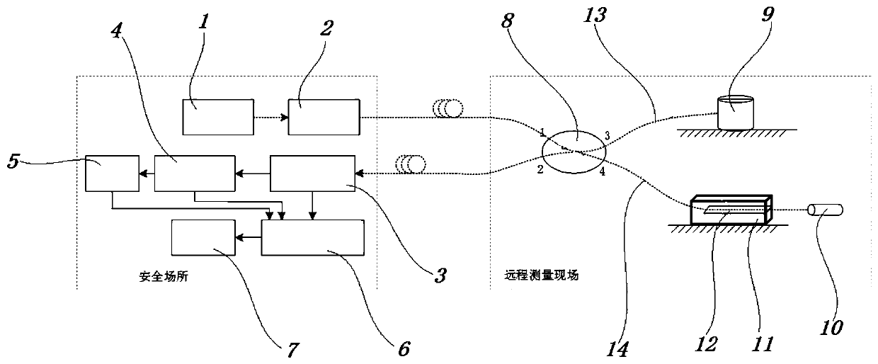
[0043] This embodiment discloses a remote externally modulated optical fiber interference vibration measurement device, including a laser emitting device, a fiber coupler 8, a housing 11, a piezoelectric shrapnel 12, a vibration probe, a Faraday rotation mirror and a processing device, a laser emitting device and an optical fiber Between the couplers 8, between the fiber interferometer and the fiber coupler 8, between the fiber coupler 8 and the processing device, fiber optic connections are used; The optical fiber coupler 8, housing 11, piezoelectric shrapnel 12, vibration probe, and Faraday rotating mirror in the example form a Michelson structure optical fiber interferometer. For the convenience of description, in this embodiment, the housing 11, piezoelectric shrapnel 12, vibration The probe and the Faraday mirror are called the main structure of the fiber optic interferometer. One end of the piezoelectric shrapnel 12 is fixed to the housing 11, and the other end is suspend...

Embodiment 2

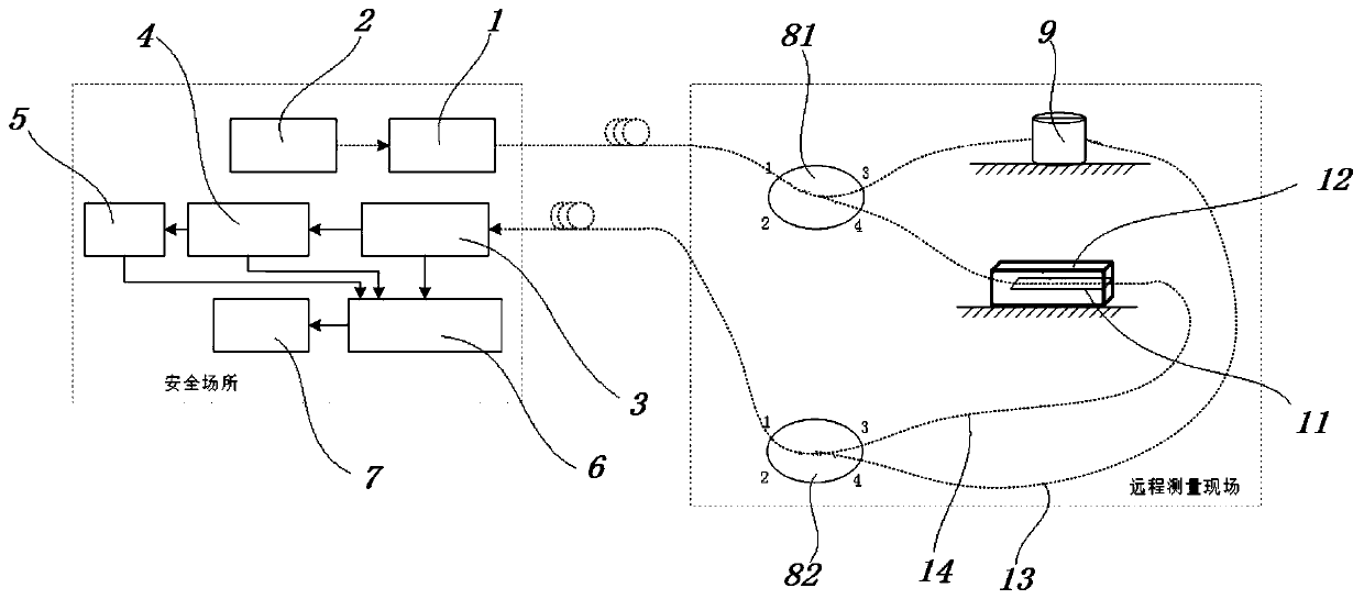
[0061] The difference between embodiment 2 and embodiment 1 is that in embodiment 2, please refer to figure 2 , the fiber optic interferometer is changed from the Michelson structure to the Mach-Zehnder structure, that is, the fiber coupler 8, the vibration probe, the piezoelectric shrapnel 12, the housing 11, and the fiber coupler 8 form the Mach-Zehnder fiber interferometer, instead of the embodiment The fiber optic coupler 8 in 1, the vibration probe, the piezoelectric shrapnel 12, the housing 11, and the Michelson fiber optic interferometer composed of the Faraday rotation mirror, that is, the main structure of the fiber optic interferometer in this embodiment does not include the Faraday rotation mirror.

[0062] The fiber coupler 8 in this embodiment includes two, the fiber coupler 8 includes a first fiber coupler 81 and a second fiber coupler 82, the laser transmitter is connected to the first fiber coupler 81, and the fiber interferometer The first fiber coupler 81 an...

Embodiment 3

[0066] Embodiment 3 discloses a remote externally modulated optical fiber interference vibration measurement method, using the remote externally modulated optical fiber interference vibration measurement device disclosed in embodiment 1 or embodiment 2, including the following steps:

[0067] In the first step, the laser 1 outputs continuous light with a wavelength of 1550nm or 1330nm suitable for optical fiber transmission.

[0068]

[0069] Among them, E L (t) represents the electric field intensity of laser 1 output continuous light, E C Indicates the amplitude value of the electric field strength, ν C represents the light frequency, represents the laser 1 phase noise that varies randomly over time, and t represents time.

[0070] In the second step, the continuous light passes through the fiber optic interferometer including the sensing arm and the reference arm, and forms an interference light signal at the output port of the fiber coupler 8:

[0071]

[0072] ...


PUM


Abstract

The invention discloses a remote external modulation optical fiber interference vibration measuring device. The device comprises a laser emitting device, an optical fiber coupler, an optical fiber interferometer main body structure and a processing device; the laser emitting device and the optical fiber coupler, the optical fiber interferometer main body structure and the optical fiber coupler, and the optical fiber coupler and the processing device are connected through optical fibers, wherein the optical fiber interferometer main body structure comprises a shell and a piezoelectric elastic sheet, one end of the piezoelectric elastic sheet is fixed on the shell, the other end of the piezoelectric elastic sheet is suspended, the shell is fixed on bed rock, and an optical fiber between theoptical fiber interferometer main body structure and the optical fiber coupler is fixed on the piezoelectric elastic sheet; when environmental vibration occurs, the shell drives the piezoelectric elastic sheet to vibrate, and a modulation signal is generated. A passive external modulation mode is used, phase modulation of the optical fiber interferometer body structure is achieved, and associatedamplitude modulation can be avoided.

Description

technical field [0001] The invention relates to the field of optical fiber interference vibration sensors, in particular to a remote externally modulated optical fiber interference vibration measurement device and method. Background technique [0002] In order to realize the measurement of physical quantities in harsh environments and avoid damage to the host of the sensing system caused by harsh environments, the host is placed in a safe place away from the sensor probe. This measurement method is called remote measurement. [0003] In the classical optical fiber interferometry technology, it is necessary to modulate the light wave to eliminate the phase blanking phenomenon of the interfering light. Light wave modulation methods include internal modulation and external modulation. Internal modulation refers to directly outputting a single-frequency excitation signal to the laser as a light source, so that the laser outputs a wavelength (or frequency) modulated light wave; ...

Claims


Application Information

Patent Timeline
Patent Type & Authority Applications(China)
IPC IPC(8): G01H9/00G01H11/08G01D5/353
CPCG01H9/004G01H11/08G01D5/35306
Inventor 于淼何禹潼王忠民崔洪亮张崇富易子川潘新建
Owner UNIV OF ELECTRONICS SCI & TECH OF CHINA ZHONGSHAN INST
Learn More