
Intelligent control system of transformers and coolers based on comprehensive perception and working method thereof

An intelligent control system, intelligent control technology, applied in transformer/inductor cooling, control/regulation system, non-electric variable control and other directions, can solve the problems of large starting current, low degree of automation, and many mechanical contacts, and achieve speed Fast, wide protection range, high precision effect

Inactive Publication Date: 2020-02-14
国网新疆电力有限公司超高压分公司 +1
View PDF4 Cites 2 Cited by
  • Summary
  • Abstract
  • Description
  • Claims
  • Application Information

AI Technical Summary

Problems solved by technology

[0002] The traditional cooling control system is composed of various relays, contactors, transfer switches and other separate components. There are many mechanical contacts and the number of analog data collection is limited. Although the important control element contactor is widely used in the automatic control circuit of the motor, it also has several obvious shortcomings.
One is that the starting current is large, and once it is jammed, it is easy to burn the coil; the other is that it is only suitable for cutting off the normal load current, and the ability to cut off the short-circuit fault current is poor. At the moment of failure or when the load is too heavy, contact adhesion often occurs The third is that the low power supply voltage leads to insufficient suction of the electromagnetic system, which causes repeated vibrations of the contacts, or the initial pressure of the contacts decreases after long-term operation, and arc welding is prone to occur when the inductive load such as a motor is closed and the vibration is violent. The probability of cooling system failure caused by contactor failure is very high; at the same time, the cooler is divided into working, auxiliary, and standby configurations, and the working state is solidified. inconvenient

Method used


Image

  • Intelligent control system of transformers and coolers based on comprehensive perception and working method thereof

Examples


specific Embodiment approach

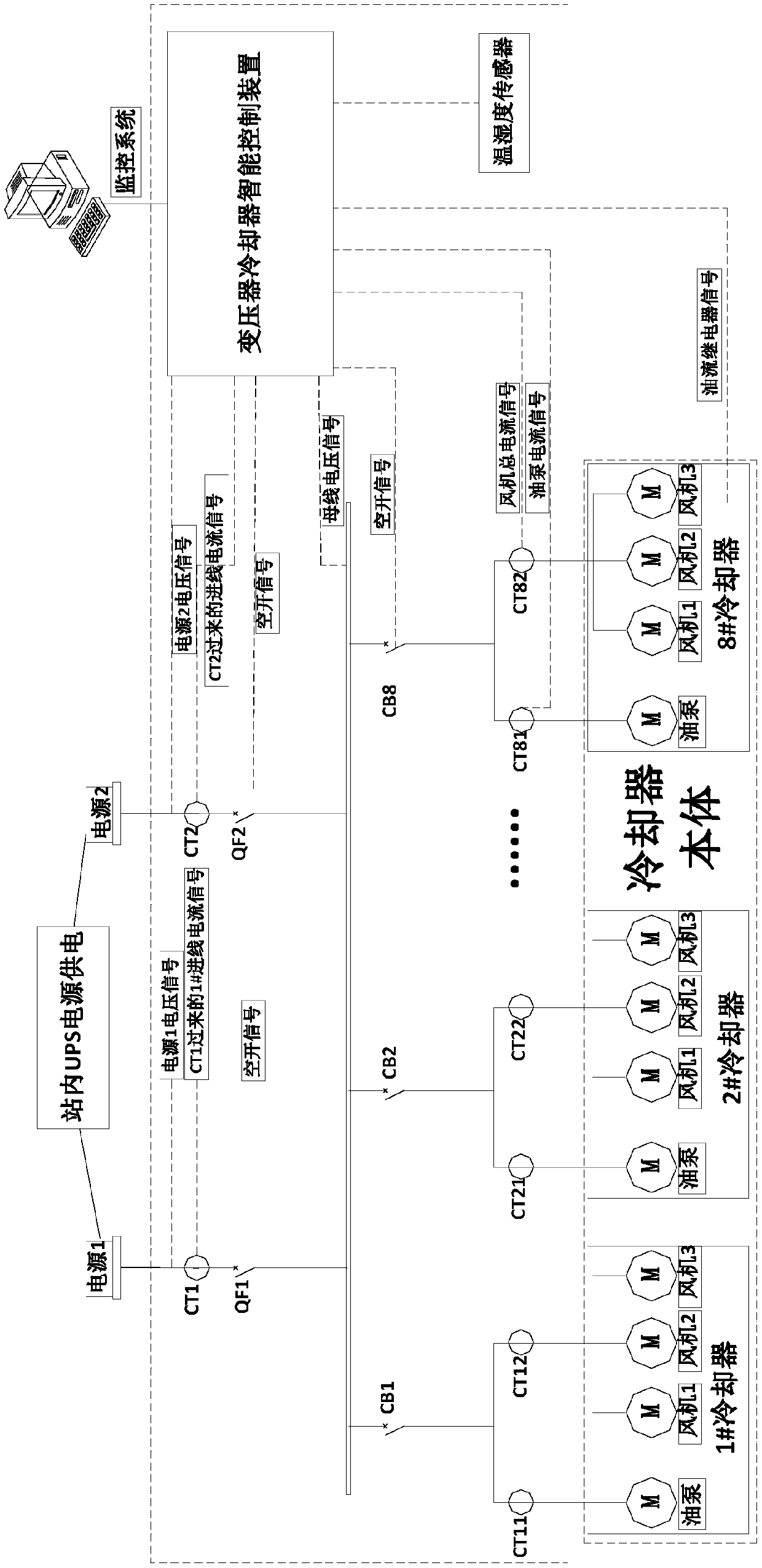
[0031] Such as figure 1 As shown, it shows the specific implementation of the present invention, based on the intelligent control system of transformer coolers with comprehensive perception, including multiple coolers, power supply I, power supply II, power supply I and power supply II are powered by UPS power supply in the station; power supply I And the power supply II is connected to all cooler circuits through the bus bar; it is characterized in that: the connection circuits between the power supply I, the power supply II and the bus bar are all equipped with feed-through transformers and air switches; the connection circuits between the bus bar and the cooler are all equipped with air switch; the connection circuit between the bus bar and the cooler includes the main circuit and two branch circuits connected in parallel on the main circuit; an air switch is installed on the main circuit, and wear-through Heart transformer;

[0032] It also includes an intelligent control...


PUM


Abstract

The invention discloses an intelligent control system of transformers and coolers based on comprehensive perception and a working method thereof. Equipment operating conditions are comprehensively judged according to multi-information of the transformers and the coolers, a reliable identification method is provided for equipment states, real-time monitoring, early warning and evaluation of a wholecooling system are realized, and intelligent management of cooler operation is realized. According to the intelligent control system of the transformers and the coolers based on the comprehensive perception, feed-through transformers and air switches are arranged on connecting circuits of a power supply I, a power supply II and a bus bar; air switches are arranged on connection circuits of the bus bar and the coolers; the connection circuits of the bus bar and the coolers include main circuits and two branch circuits connected in parallel on the main circuits; air switches are installed on the main circuits, feed-through transformers are arranged on the two branch circuits correspondingly connected with an oil pump and a fan; and a transformer and cooler intelligent control device is further included, and the transformer and cooler intelligent control device comprises a central MCU, multiple sampling circuits and multiple voltage transformers.

Description

technical field [0001] The invention relates to a transformer cooling system monitoring device, which is specifically used for the monitoring and control of the transformer cooler system. Background technique [0002] The traditional cooling control system is composed of various relays, contactors, transfer switches and other separate components. There are many mechanical contacts and the number of analog data collection is limited. Although the important control element contactor is widely used in the automatic control circuit of the motor, it also has several obvious shortcomings. One is that the starting current is large, and once it is jammed, it is easy to burn the coil; the other is that it is only suitable for cutting off the normal load current, and the ability to cut off the short-circuit fault current is poor. At the moment of failure or when the load is too heavy, contact adhesion often occurs The third is that the low power supply voltage leads to insufficient s...

Claims


Application Information

Patent Timeline
IPC IPC(8): G05D23/20H01F27/08H01F27/12
CPCG05D23/20H01F27/085H01F27/12
Inventor 楚修楠张晗蔡晶左稳曹文东石海珍邓剑伟樊五鹏乔佳男李高鹏
Owner 国网新疆电力有限公司超高压分公司
Learn More