Eureka AIR delivers breakthrough ideas for toughest innovation challenges, trusted by R&D personnel around the world.

High-reliability energy storage system and energy storage container

An energy storage system and box technology, applied in electrical components, electrochemical generators, fire rescue, etc., can solve the problems of redundant and wasteful distribution wiring of battery clusters, affecting the economic benefits of energy storage systems, and reducing battery life, etc. Achieve the effects of avoiding short circuit of battery wiring, reducing unit thermal management space and energy consumption, and reducing manufacturing and processing costs

Pending Publication Date: 2020-02-14
GREE ELECTRIC APPLIANCES INC
View PDF0 Cites 6 Cited by
  • Summary
  • Abstract
  • Description
  • Claims
  • Application Information

AI Technical Summary

Problems solved by technology

[0003] In terms of structural layout of conventional container energy storage systems, all battery clusters are often stacked in one cabin, which poses a great safety hazard. Moreover, batteries are the main heat source of the energy storage system. Centralized placement will increase the difficulty of thermal management. The problem of unreasonable design and configuration, as well as lengthy and wasteful power distribution wiring of some battery clusters and crowded wiring, resulting in redundant power consumption or poor heat dissipation, reducing battery life and system efficiency, and further affecting the economic benefits of the energy storage system. Serious Risk of fire due to thermal runaway

Method used


Image

  • High-reliability energy storage system and energy storage container

Examples


Embodiment Construction

[0028] In order to make the object, technical solution and advantages of the present invention clearer, the present invention will be further described in detail below in conjunction with the accompanying drawings and embodiments. It should be understood that the specific embodiments described here are only used to explain the present invention, not to limit the present invention.

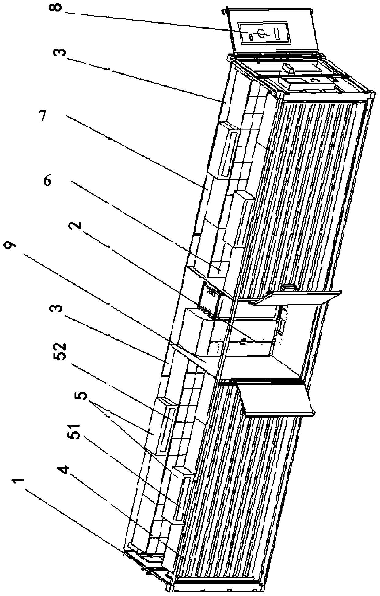
[0029] Such as figure 1 The energy storage system shown includes a box body 1, and the inside of the box body 1 forms a device cavity 2 and at least two battery cavities 3, at least one of the battery cavities 3 is located on the first side of the device cavity 2, and all the remaining The battery cavity 3 is located on the second side of the equipment cavity 2, and there is a set between the equipment cavity 2 and its adjacent battery cavity 3 and / or between two adjacent battery cavities 3 partition 9, and the wiring harness of each battery cavity 3 passes through the partition 9 and then is wire...


PUM


Abstract

The invention provides a high-reliability energy storage system and an energy storage container. The energy storage system comprises a box body, wherein an equipment cavity and at least two battery cavities are formed in the box body, and at least one battery cavity is located on a first side of the equipment cavity. The invention provides an energy storage system with high reliability and an energy storage container. Electrical equipment and a battery cluster are respectively arranged in the equipment cavity and a battery cavity, the safety risk is effectively reduced, so the risk of fire isavoided, the size of a battery cabin is reduced relative to the whole box body, a front-back ventilation mode is adopted, an indoor unit can perform accurate heat dissipation of the battery cluster, the battery clusters are symmetrically arranged at two ends of an equipment cabin, short circuit of battery wiring caused by condensation is effectively avoided, so an electrical wiring distance is symmetrically shortened, line loss of a power line and a sampling line of a battery system is reduced, acquisition precision and communication stability are improved, and manufacturing and processing cost is reduced due to the standard consistent wiring harness design.

Description

technical field [0001] The invention relates to the technical field of electrical equipment, in particular to an energy storage system and an energy storage container with high reliability. Background technique [0002] As a key technology of the Energy Internet system, online energy storage is more and more widely used in scenarios such as shifting peaks and filling valleys near the user side, improving power quality, power demand response, reducing capacity and increasing distribution, and emergency power supply; the energy storage system is mainly composed of It consists of battery clusters, energy storage converters, energy management systems, and auxiliary systems such as thermal management, power distribution, and fire protection; in order to install and deploy energy storage systems flexibly and conveniently, the components of the energy storage system are often integrated in the form of containers. [0003] In terms of structural layout of conventional container ener...

Claims


Application Information

Patent Timeline
Patent Type & Authority Applications(China)
IPC IPC(8): H01M2/10H01M10/613H01M10/6563A62C3/16H01M50/20
CPCH01M10/613H01M10/6563A62C3/16H01M50/20Y02E60/10
Inventor 赵志刚蒋世用段科汪高峰何意吴超周志红
Owner GREE ELECTRIC APPLIANCES INC
Why Eureka
Eureka Blog
Learn More