
Transmission mechanism for spaceflight

A transmission mechanism, permanent magnet technology, applied in electromechanical devices, electric components, electric brakes/clutches, etc., can solve the problems of friction loss, lubrication pollution, mechanical fatigue, etc., and achieve the effect of stable output

Inactive Publication Date: 2020-02-14
ZHONGBEI UNIV
View PDF4 Cites 0 Cited by
  • Summary
  • Abstract
  • Description
  • Claims
  • Application Information

AI Technical Summary

Problems solved by technology

[0003] According to the different types of transmission mechanisms, the current aerospace precision transmission mechanisms include screw transmission and gear transmission. Mechanical gear transmission is widely used in various fields of society due to its stable transmission ratio and large transferable torque. Due to processing and installation errors, Mechanical straight and helical bevel gears have relatively large vibration and noise in transmission, while spiral bevel gears have high transmission accuracy but high processing costs and expensive prices
Moreover, mechanical bevel gears rely on the meshing between teeth to transmit torque, which brings irreversible problems to gear transmission, such as mechanical fatigue, friction loss, lubrication pollution, large vibration and noise, etc.

Method used


Image

  • Transmission mechanism for spaceflight
  • Transmission mechanism for spaceflight
  • Transmission mechanism for spaceflight

Examples


Embodiment 1

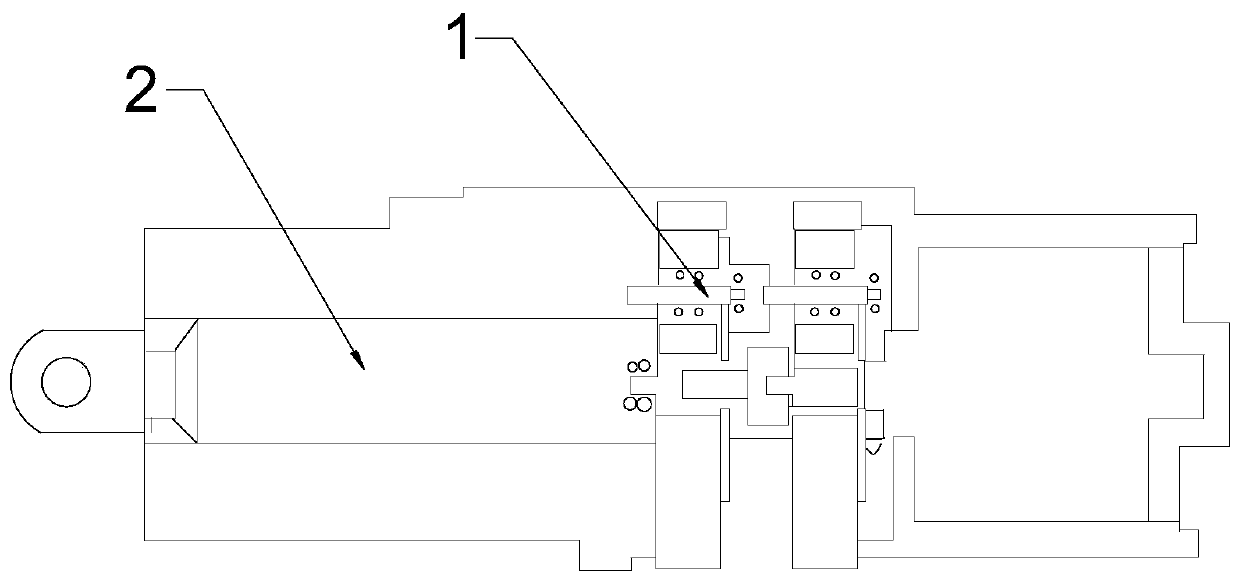
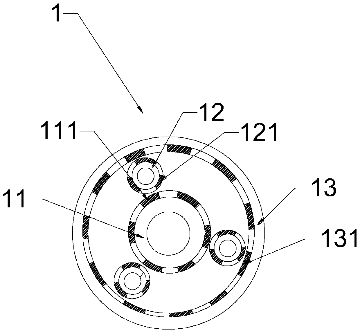
[0039] combine Figure 1-2 , a transmission mechanism for aerospace, including a planetary gear set 1 and a ball screw pair 2, the ball screw pair 2 is connected to the planetary gear set 1, and the planetary gear set 1 and the ball screw pair 2 are linear Arranged, the planetary gear set 1 includes a sun gear 11, a planetary gear 12, an inner ring gear 13 and a permanent magnet. The rotation direction of the meshing gear is opposite. The planetary gear 12 and the ring gear 13 are ring gear structures. The rotation direction of the planetary gear 12 and the ring gear 13 is the same. Axis settings.

[0040] Described permanent magnet comprises the first permanent magnet 111 of radial magnetization, the second permanent magnet 121 and the 3rd permanent magnet 131, and the outer surface of described sun gear 11 is provided with first permanent magnet 111, and the outer surface of described planetary gear 12 The second permanent magnet 121 is arranged on the surface, and the thi...

Embodiment 2

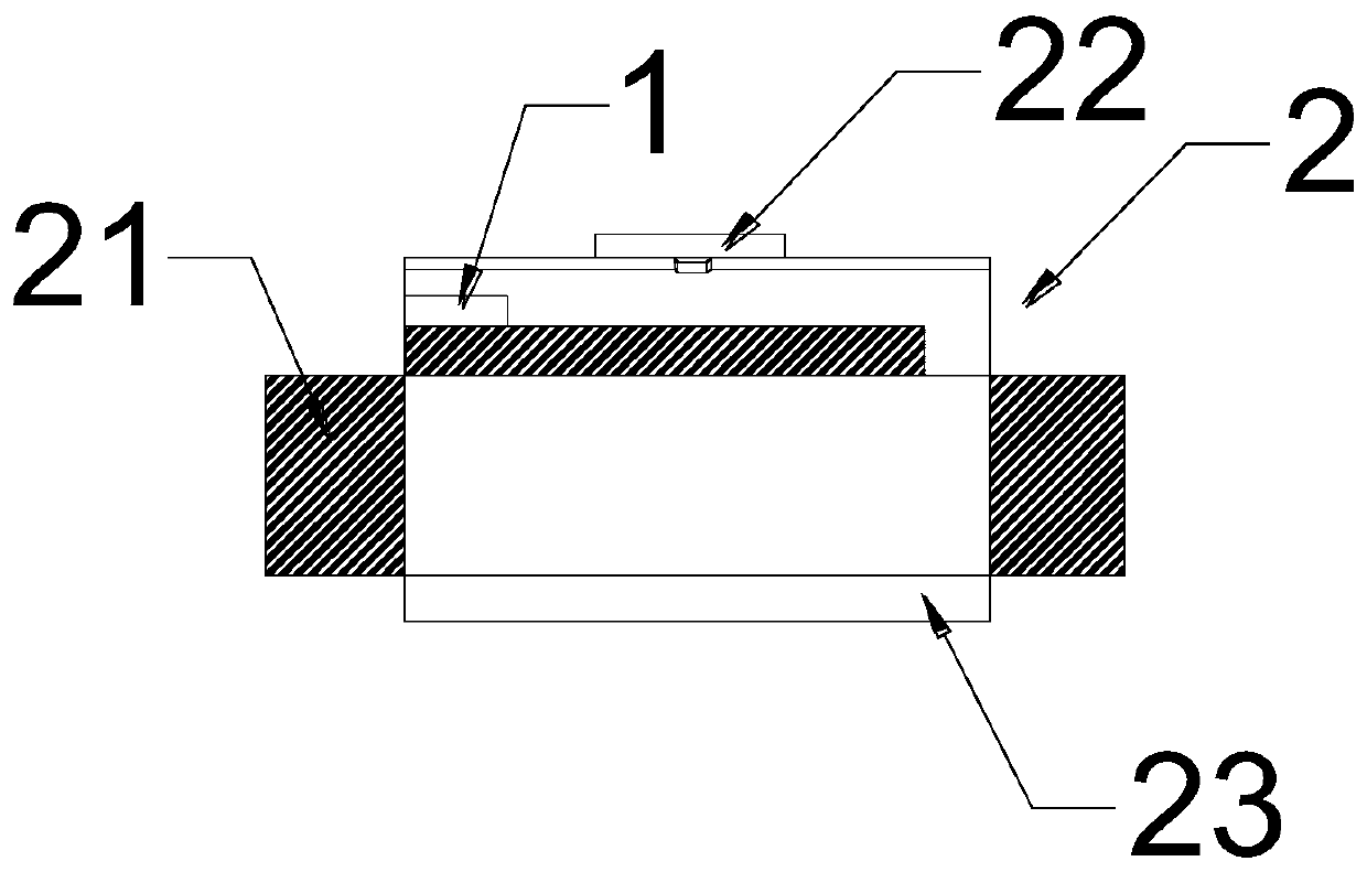
[0043] combine figure 1 and image 3 , the ball screw pair 2 includes a roller screw 21, a nut 23 and a flat key 22, one end of the roller screw 21 is connected to the planetary gear set 1, the nut 23 is sleeved on the ball screw, the The flat key 22 is arranged on the nut 23, and the nut 23 adopts a combined double nut 23 composed of two nuts 23 without axial clearance.

[0044] Combine the planetary gear set 1 and the ball screw pair 2, and drive the planetary gear set 1 through the motor. The planetary gear set 1 is equivalent to the reducer of the ball screw pair 2, so that the screw runs more smoothly and realizes the ball screw pair 2. The different transmission ratios make the ball screw 21 have a strong bearing capacity and life span, and have higher rotational speed and angular acceleration, which can be applied to various conditions and realize the miniaturization and light weight of the transmission mechanism.

Embodiment 3

[0046] On the basis of Embodiment 1, the planetary gear is connected to the planetary carrier, and the sun gear, the planetary carrier and the internal gear are coaxially arranged.

[0047] The sun gear radius R 1 , planet wheel radius R 2 and ring gear radius R 3 Meet: R 1 +2R 2 = R 3 .

[0048] The number of pole pairs of the sun gear P 1 , Planetary gear pole pair number P 2 and the number of pole pairs of the inner ring gear P 3 Satisfied:P 1 +2P 2 =P 3 .

[0049] The radius of the planet carrier satisfies: R 4 =(R 3 +R 1 ) / 2.

[0050] The number of the planetary wheels satisfies: in And a, b∈N, 1≤N≤4.

[0051] The sun gear angular velocity ω 1 , planet carrier angular velocity ω 4 and the angular velocity of the ring gear ω 3 satisfy:

[0052] The angular velocity of the ball screw ω G satisfy: Among them, d 1 is the screw diameter, d 2 is the nut diameter.

[0053] Both the planetary gear and the sun are pasted with magnetic pieces on the ...


PUM


Abstract

The invention relates to a transmission mechanism for spaceflight, which comprises a planetary gear set and a ball screw pair, wherein the ball screw pair is connected with the planetary gear set, theplanetary gear set and the ball screw pair are arranged in a linear mode, the planetary gear set comprises a sun gear, a planet gear, an inner gear ring and a permanent magnet, the sun gear and the inner gear ring are coaxially arranged, the permanent magnet comprises a first permanent magnet, a second permanent magnet and a third permanent magnet, the first permanent magnet is arranged on the outer surface of the sun gear, the second permanent magnet is arranged on the outer surface of the planet gear, the third permanent magnet is arranged on the inner surface of the inner gear ring, and the permanent magnet comprises at least one magnetic pole pair; the ball screw pair comprises a roller screw, a nut and a flat key. According to the transmission mechanism provided by the invention, torque transmission is carried out through magnetic pull coupled by multiple magnetic fields, and volume miniaturization and light weight of the transmission mechanism are realized.

Description

technical field [0001] The invention belongs to the technical field of transmission mechanisms, and in particular relates to a transmission mechanism for aerospace. Background technique [0002] As the link between the power system and the working mechanism, the transmission mechanism is widely used in various types of aerospace vehicles. As the basic core components of major aerospace equipment, there is still a large gap between the performance of my country's aerospace transmission mechanisms and foreign products, and there are still technical bottlenecks that restrict development. Due to the application of a large number of precision transmission mechanisms in aerospace equipment, these devices The performance of aerospace equipment directly determines the working performance of aerospace equipment. Therefore, the development of the design and manufacturing technology of aerospace precision transmission mechanisms marks the development level of a country's aerospace indus...

Claims


Application Information

Patent Timeline
Patent Type & Authority Applications(China)
IPC IPC(8): H02K49/10
CPCH02K49/102
Inventor 王志坚杜文华王俊元曾志强王日俊张纪平党长营
Owner ZHONGBEI UNIV
Learn More