Shielding member and apparatus for single crystal growth

A growth device and crystal growth technology, applied in the direction of single crystal growth, single crystal growth, crystal growth, etc., to achieve the effect of suppressing radiation

Active Publication Date: 2020-02-21
RESONAC CORP
View PDF4 Cites 0 Cited by
  • Summary
  • Abstract
  • Description
  • Claims
  • Application Information

AI Technical Summary

Problems solved by technology

Therefore, it is difficult to generate a temperature difference between the raw material and the growth surface

Method used


Image

  • Shielding member and apparatus for single crystal growth
  • Shielding member and apparatus for single crystal growth
  • Shielding member and apparatus for single crystal growth

Examples


no. 1 Embodiment approach

[0051] "Single crystal growth device"

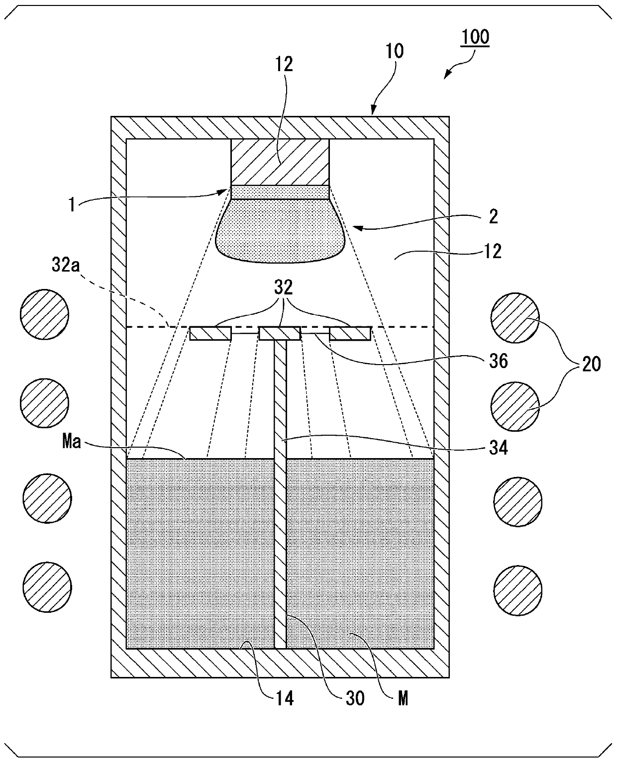
[0052] figure 1 It is a schematic cross-sectional view showing a preferred example of the single crystal growth apparatus of the first embodiment. figure 1 In , for easy understanding, the raw material M, the seed crystal 1 and the single crystal 2 are shown together. figure 1 The illustrated single crystal growth apparatus 100 includes a crystal growth container 10 , a coil (heating unit) 20 , and a shield member 30 .

[0053] The crystal growth container 10 has a space inside. The raw material M is filled in the inner bottom surface of the crystal growth container 10 . The inner bottom surface of the crystal growth container 10 serves as a raw material storage portion 14 . A crystal setting unit 12 is provided at a position facing the raw material M filled in the raw material storage unit 14 . The crystal setting part 12 is a part where the seed crystal 1 is set. For example, the crystal installation portion 12 protrudes toward t...

no. 2 Embodiment approach

[0076] "Single crystal growth device"

[0077] Figure 6 It is a schematic cross-sectional view of the single crystal growth apparatus of the second embodiment. For easy understanding, Figure 6 The raw material M, the seed crystal 1 and the single crystal 2 are simultaneously shown in FIG. figure 1 The illustrated single crystal growth apparatus 101 includes a crystal growth container 10 , a coil (heating unit) 20 , and a shield member 70 . The shape of the shielding member 70 and figure 1 The single crystal growth apparatus 100 shown is different. Other structures are the same, with the same symbols attached, and descriptions are omitted.

[0078] The shield member 70 includes a plurality of shield plates 72 , support portions 74 , and connection portions 76 . A plurality of shielding plates 72 become 2 sections, which is the same as figure 1 The shielding member 30 shown is different. Figure 7 It is a figure which projected the shielding member 70 of 2nd Embodiment...

Embodiment 1

[0092] "Example 1"

[0093] First, a crystal growth container provided with a columnar inner space was prepared. Then, SiC in a powder state was filled as a raw material from the inner bottom surface of the crystal growth container to a position of 30% of the height of the inner space. The crystal installation part was set as a circle with a diameter of 6 inches in plan view.

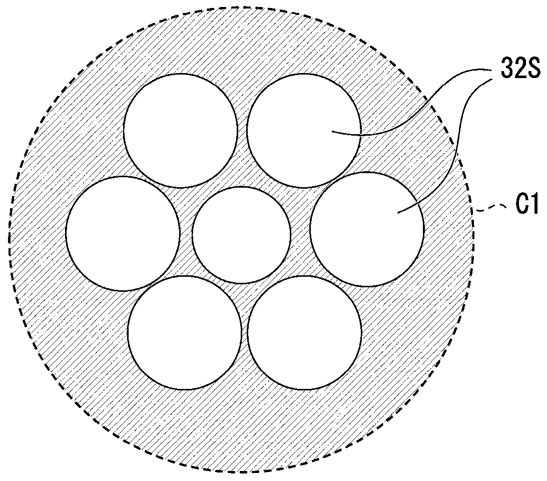
[0094] Furthermore, a shielding member is provided between the raw material and the crystal installation part. As the shielding member, three circular shielding plates in plan view are arranged in a hexagonal close-packed arrangement, that is, they are arranged on the same plane at equal distances from each other around the support portion. The respective areas of the shielding plates were set to 17% of the area of ​​the inner bottom of the crystal growth container. In addition, the height of the arrangement of the shielding plates is designed so that the shielding ratio of the projected surface obta...


PUM

PropertyMeasurementUnit
shading coefficientaaaaaaaaaa

Abstract

The invention relates to a shielding member and an apparatus for single crystal growth. The shielding member is placed in an apparatus for single crystal growth, wherein the apparatus includes a crystal growth container including a raw material accommodating portion which accommodates a raw material in an inner bottom portion, and a crystal installation portion facing the raw material accommodating portion, and a heating unit that is configured to heat the crystal growth container, the apparatus for single crystal growth grows a single crystal of the raw material on a crystal installed on thecrystal installation portion by sublimating the the raw material from the raw material accommodating portion; the shielding member is placed between the raw material accommodating portion and the crystal installation portion, and includes a plurality of shielding plates, wherein each area of the plurality of shielding plates is 40% or less of a base area of the crystal growth container, and wherein, in a case where the raw material accommodating portion is filled with a raw material, a shielding ratio provided by a projection surface of the plurality of shielding plates, which is projected onan internal circle of the raw material accommodating portion at a raw material surface, is 0.5 or more.

Description

technical field [0001] The present invention relates to a shield member and a single crystal growth device. [0002] This application claims priority based on Patent Application No. 2018-149281 filed in Japan on August 8, 2018, the contents of which are incorporated herein by reference. Background technique [0003] Compared with silicon (Si), silicon carbide (SiC) has an insulation breakdown electric field that is an order of magnitude larger and a band gap that is three times larger. In addition, silicon carbide (SiC) has characteristics such as thermal conductivity about three times higher than that of silicon (Si). Silicon carbide (SiC) is expected to be applied to power devices, high-frequency devices, high-temperature operating devices, and the like. [0004] Devices such as semiconductors use SiC epitaxial wafers in which epitaxial films are formed on SiC wafers. The epitaxial film formed on the SiC wafer by chemical vapor deposition (Chemical Vapor Deposition: CVD...

Claims


Application Information

Patent Timeline
Patent Type & Authority Applications(China)
IPC IPC(8): C30B23/00C30B29/36
CPCC30B23/00C30B29/36C30B23/06C30B23/005C30B35/007
Inventor 藤川阳平
Owner RESONAC CORP
Why Eureka
Try Eureka