
Sensor system for determining temperature and rotational characteristics of rotating element

A temperature sensor and rotating element technology, applied in the field of sensor systems, can solve the problems of permanent magnet demagnetization, cost, lack of measurement information, limit motor, etc.

Pending Publication Date: 2020-02-21
ROBERT BOSCH GMBH
View PDF9 Cites 2 Cited by
  • Summary
  • Abstract
  • Description
  • Claims
  • Application Information

AI Technical Summary

Problems solved by technology

In particular, the lack of measured information on the rotor temperature limits the behavior of the electric machine and necessitates modeling with corresponding complexity and inaccuracies, see DE 10 2014 213 103
In the case of constant field synchronous motors, excessive rotor temperatures lead to demagnetization of the permanent magnets

Method used


Image

  • Sensor system for determining temperature and rotational characteristics of rotating element
  • Sensor system for determining temperature and rotational characteristics of rotating element
  • Sensor system for determining temperature and rotational characteristics of rotating element

Examples


Embodiment Construction

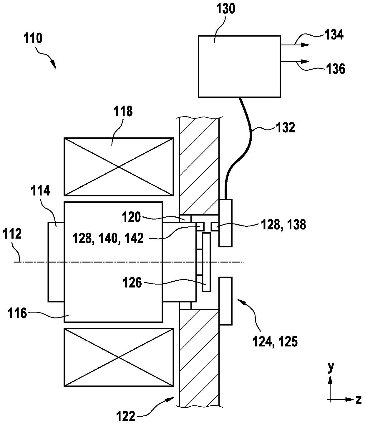
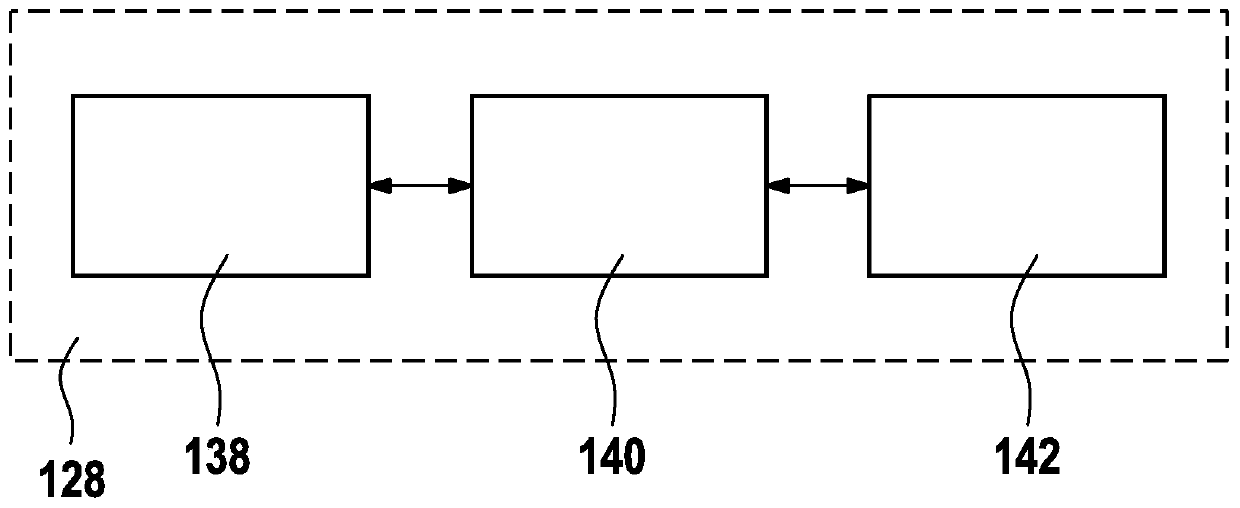
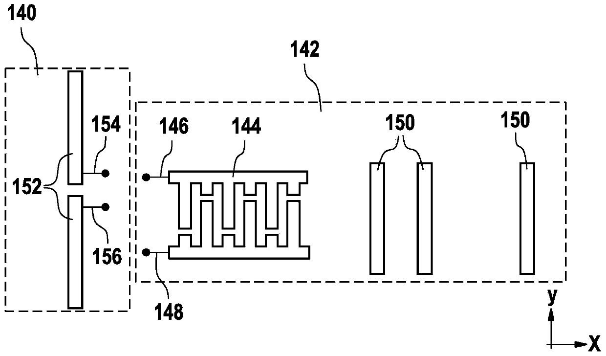
[0051] figure 1 A schematic illustration of a sensor system 110 according to the invention according to an embodiment is shown. The sensor system 110 is provided for determining at least one rotational characteristic of a rotational element 114 about at least one rotational axis 112 . In particular, sensor system 110 may be provided for use in a motor vehicle. In particular, sensor system 110 may be provided for sensing at least one rotational characteristic of the camshaft. Sensor system 110 may be configured, for example, to sense the angular position of a camshaft. Correspondingly, the rotating element 114 can be, for example, a shaft. In the case of the shown constant field synchronous machine, the shaft may carry permanent magnets 116 . The stator coil pack 118 can be arranged cylindrically around the permanent magnet 116 . The output device can be arranged in the negative z-direction and is not shown again. On the side opposite the output, a B bearing 120 can be ar...


PUM


Abstract

The invention relates to a sensor system for determining the temperature and rotational characteristics of a rotating element about an axis of rotation. The sensor system includes: a sensor; temperature sensor, and a temperature sensor arranged to sense a temperature of the rotating element, wherein the temperature sensor has an interrogation unit, an antenna and a sensor element, the interrogation unit is provided for transmitting an electrical transmission signal to the antenna and for receiving an electrical reception signal from the antenna, the antenna is arranged to generate a surface wave in the sensor element based on the transmission signal and to generate a reception signal based on the surface wave reflected in the sensor element, and the reception signal is proportional to thetemperature of the rotating element. The sensor system also includes an inductive position sensor configured to sense information about a rotational characteristic of the rotating element. The sensorsystem further comprises an evaluation unit arranged for generating a first signal having information about the sensed temperature and a second signal having information about the rotational characteristic.

Description

technical field [0001] The invention relates to a sensor system for determining the temperature and at least one rotational property of a rotational element about at least one rotational axis. Background technique [0002] A large number of sensors for sensing at least one rotational property of a rotating element are known from the prior art. Examples of such sensors are described in Konrad Reif (ed.): Sensoren im Kraftfahrzeug, 2nd edition, 2012, pp. 63-74 and pp. 120-129. For example, the position of a camshaft of an internal combustion engine relative to a crankshaft with a so-called phase transmitter wheel can be determined by means of Hall sensors. [0003] For example, for traction in electric vehicles, often either asynchronous or synchronous electric machines are used, which each consist of a stationary stator and a rotating rotor. The stator usually carries three winding wires which are offset from one another, for example by 120° / p, where p stands for the number...

Claims


Application Information

Patent Timeline
Patent Type & Authority Applications(China)
IPC IPC(8): G01K11/26G01P3/487G01D5/20
CPCG01K11/265G01P3/487G01D5/20G01D21/02H02P29/60H02P6/16G01K13/08
Inventor F·于特尔默伦R·鲁萨诺夫
Owner ROBERT BOSCH GMBH
Learn More