
Ultrafast scanning calorimeter with modular structure

A scanning calorimeter, modular technology, applied in the direction of instruments, measuring devices, scientific instruments, etc., can solve the problems of single sample experiment environment, poor flexibility, too expensive for manufacturers and customers, achieve high flexibility, avoid heat Lag effect

Inactive Publication Date: 2020-02-21
SHEYANG RES INST OF NANJING UNIV +1
View PDF8 Cites 5 Cited by
  • Summary
  • Abstract
  • Description
  • Claims
  • Application Information

AI Technical Summary

Problems solved by technology

At present, the only commercialized fast scanning calorimeter on the market is the Flash DSC produced by Metter-Toledo. Its product appearance structure inherits the integrated design of the traditional DSC. This integrated box design largely Limiting Applications of Ultrafast Scanning Calorimetry
The integrated design makes the position of each component relatively fixed, and cannot be adjusted according to specific experimental requirements. The flexibility is poor, which greatly reduces the possibility of combining with other technologies. At the same time, due to the limitation of the overall structure design of the instrument, the sample experimental environment is relatively simple.
In addition, there is little room for improvement in instrument technology, and each change is too expensive for manufacturers and customers

Method used


Image

  • Ultrafast scanning calorimeter with modular structure
  • Ultrafast scanning calorimeter with modular structure
  • Ultrafast scanning calorimeter with modular structure

Examples


Embodiment 1

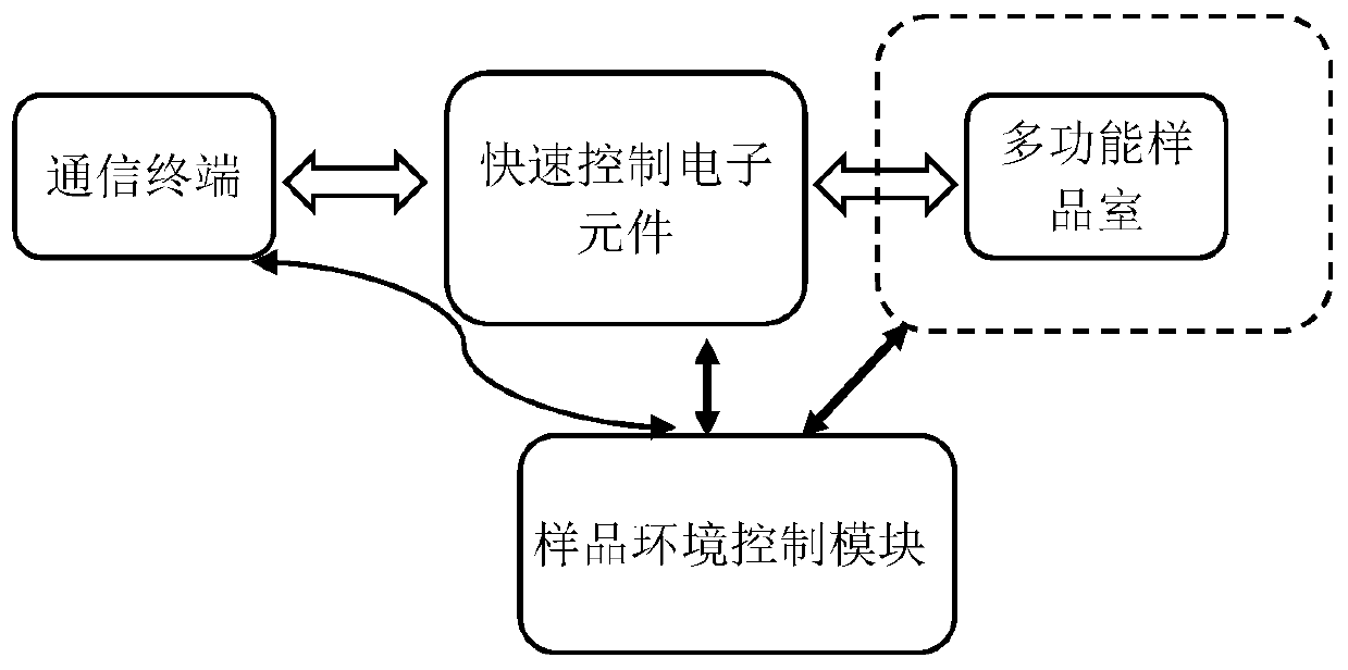
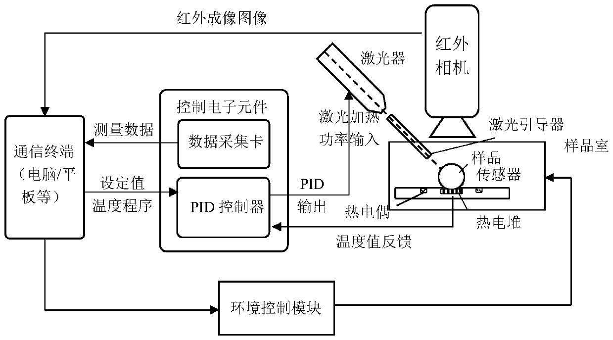
[0043] This example presents a modular laser heating ultrafast calorimeter, as figure 2 shown.

[0044] The fast scanning calorimeter includes an FSC sample chamber, a chip sensor located in the FSC sample chamber for carrying the sample, a laser heater for heating the sample, an infrared camera for taking images of the sample, a communication terminal, and control electronics.

[0045] The center of the FSC sample chamber is provided with a see-through window as an optical path, and the laser heater and infrared camera are located on the top of the window and can be aimed at the samples in the FSC sample chamber.

[0046] The infrared camera is connected to the communication terminal, and the photographs taken are sent to the communication terminal through infrared imaging; one end of the control electronic component is connected to the communication terminal, and the other end is respectively connected to the laser heater and the chip sensor. The control electronic compone...

Embodiment 2

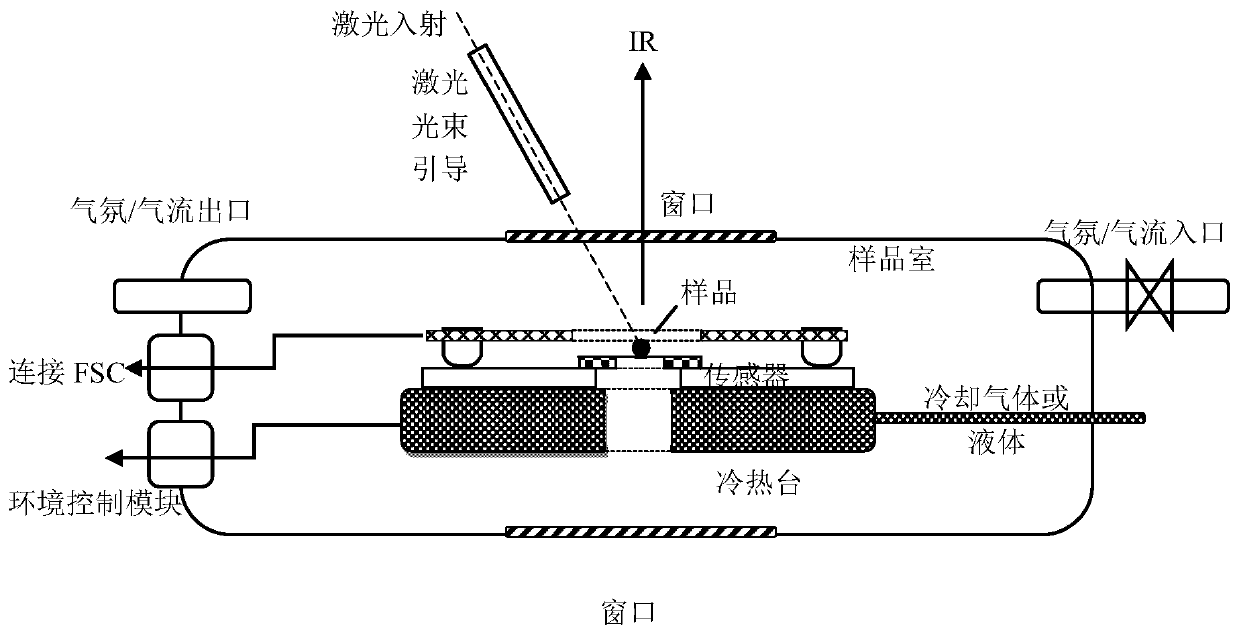
[0065] This example gives a cold and hot bench type ultra-fast calorimeter, and its module diagram is as follows Image 6 shown. Including hot and cold stage sample room, sample room environment temperature control system, fast control electronic components and communication terminal.

[0066] Among them, the structure of the cold and hot table type sample chamber refers to CN201310499799.9. The sample chamber is a sealed cavity, which specifically includes a cold and hot table containing a heating element and a refrigerant circulation pipe and a transmission hole, a transmission window, a reflection window, and a film sensor terminal. , thin film sensor signal line interface, refrigerant inlet, refrigerant outlet, temperature control signal interface of cold and hot stage and atmosphere channel, reflection window and transmission window are located on the wall opposite to the sealed sample chamber.

[0067] The reflection window and transmission window of the sample chamber ...

Embodiment 3

[0079] At present, the minimum permissible cooling temperature of the hot and cold bench type ultrafast scanning calorimeter is -100°C. When the test temperature needs to be lower, the sample chamber with enhanced cooling can be used.

[0080] This example presents a cooling-enhanced ultrafast scanning calorimeter, the block diagram of which is shown in Figure 7 As shown, it includes a sealed tubular sample chamber, an environmental control module, fast control electronics, and a communication terminal.

[0081] The sealed tubular sample chamber includes a thin-walled sealed tube, a sensor bracket, a stainless steel bracket, connecting wires, an atmosphere inlet and outlet, an upper cover and a circuit interface.

[0082] The thin-walled sealing tube is usually made of stainless steel, and the tube wall is about 0.5mm, which ensures the minimum temperature difference between the atmosphere inside and outside the tube, and at the same time, the tube can withstand a vacuum pres...


PUM

PropertyMeasurementUnit
diameteraaaaaaaaaa
diameteraaaaaaaaaa

Abstract

The invention discloses an ultrafast scanning calorimeter with a modular structure. The ultrafast scanning calorimeter comprises a multifunctional sample chamber, a sample environment control module,a fast control electronic element and a communication terminal; the communication terminal, the fast control electronic element and the multifunctional sample chamber are in signal connection in sequence; the environment control module is connected with each of the communication terminal, the fast control electronic element and the multifunctional sample chamber; and a chip sensor for bearing a sample is arranged in the multifunctional sample chamber. The ultrafast scanning calorimeter with the modular structure can change the components according to different experimental requirements and perform multi-party combination, and has higher flexibility, mobility and experimental pertinence: the temperature control can be performed by using an analog signal controller or a digital microcontroller in a switching manner; the volume, appearance design and environment control mode of the sample chamber can be changed in a targeted manner, and the experimental test in harsh, cold, high-pressureor low-pressure environments with limited space can be met; and meanwhile, the device can be used together with other auxiliary characterization equipment to measure calorimetric information, opticalinformation and the like of the sample in situ.

Description

technical field [0001] The invention belongs to the field of detection equipment, in particular to an ultrafast scanning calorimeter with a modular structure. Background technique [0002] Traditional scanning calorimeters are mostly designed as an integrated structure to facilitate mass production and customer universality, but at the same time it also reduces the diversification and functionality of the calorimeter. When different test temperature ranges, different sample chambers, and different technologies are required, it is usually necessary to produce (manufacturer) or purchase (customer) a new model, which consumes a lot of financial and material resources. Compared with traditional scanning calorimeters, ultra-high-speed scanning calorimeters aimed at high-tech industries are more inclined to scientific research equipment, require more targeted functions, and are more expensive, which is lower than ordinary traditional calorimeters. several times. At present, the ...

Claims


Application Information

Patent Timeline
Patent Type & Authority Applications(China)
IPC IPC(8): G01N25/12G01N25/04G01N25/14G01N21/3563
CPCG01N25/12G01N25/04G01N25/147G01N21/3563
Inventor 周东山朱逸夫姜菁薛奇罗少川王晓亮江伟季青
Owner SHEYANG RES INST OF NANJING UNIV
Learn More