Polarization multiplexing waveguide display device

A display device, polarization multiplexing technology, applied in the directions of optical waveguides, light guides, instruments, etc., to achieve the effect of large field of view, high transparency, and high-efficiency color image transmission

Inactive Publication Date: 2020-02-21
SOUTHEAST UNIV
View PDF9 Cites 12 Cited by
  • Summary
  • Abstract
  • Description
  • Claims
  • Application Information

AI Technical Summary

Problems solved by technology

[0004] Although the waveguide structure made of PVG itself can provide a large field of view, due to the influence of the refractive index

Method used


Image

  • Polarization multiplexing waveguide display device
  • Polarization multiplexing waveguide display device
  • Polarization multiplexing waveguide display device

Examples


Embodiment 1

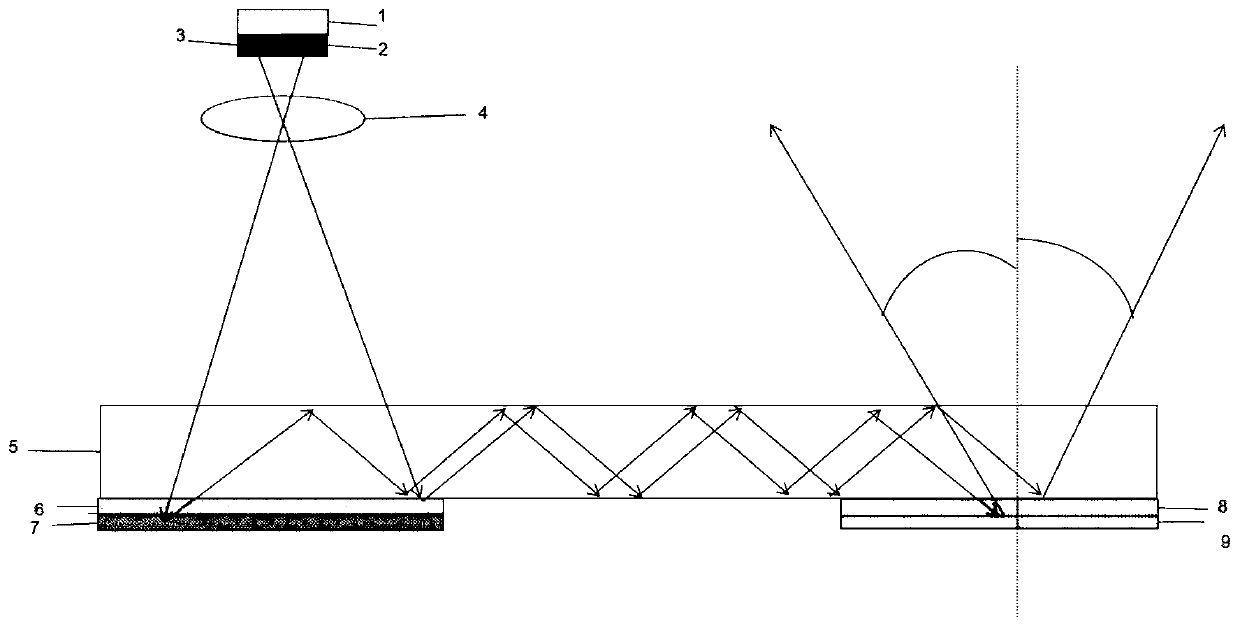
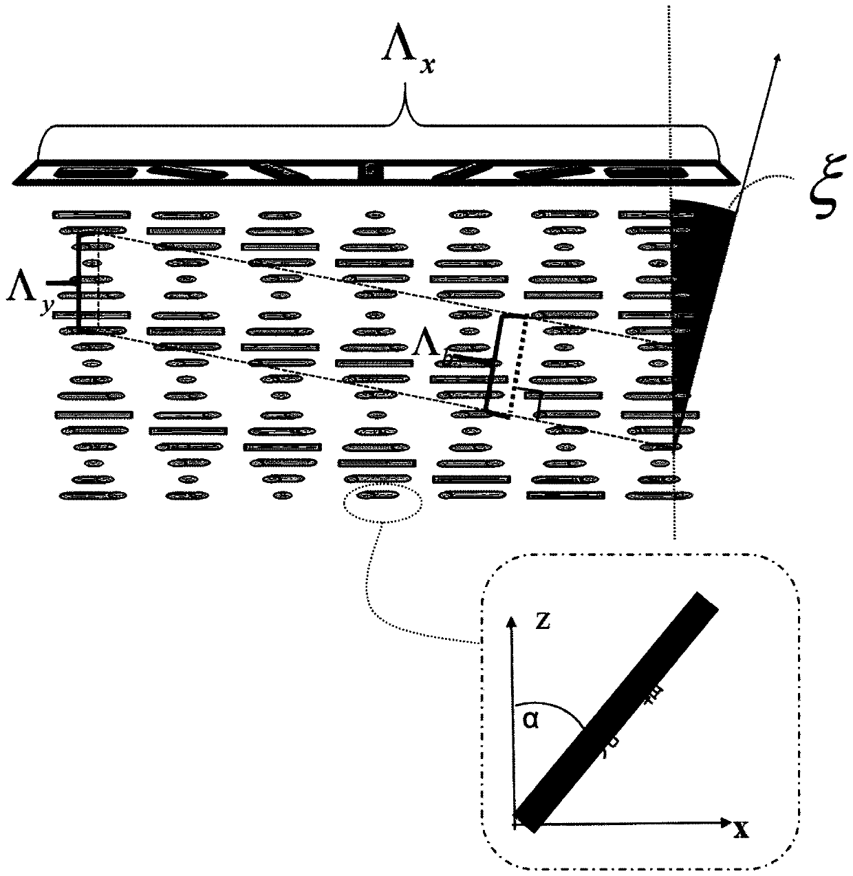
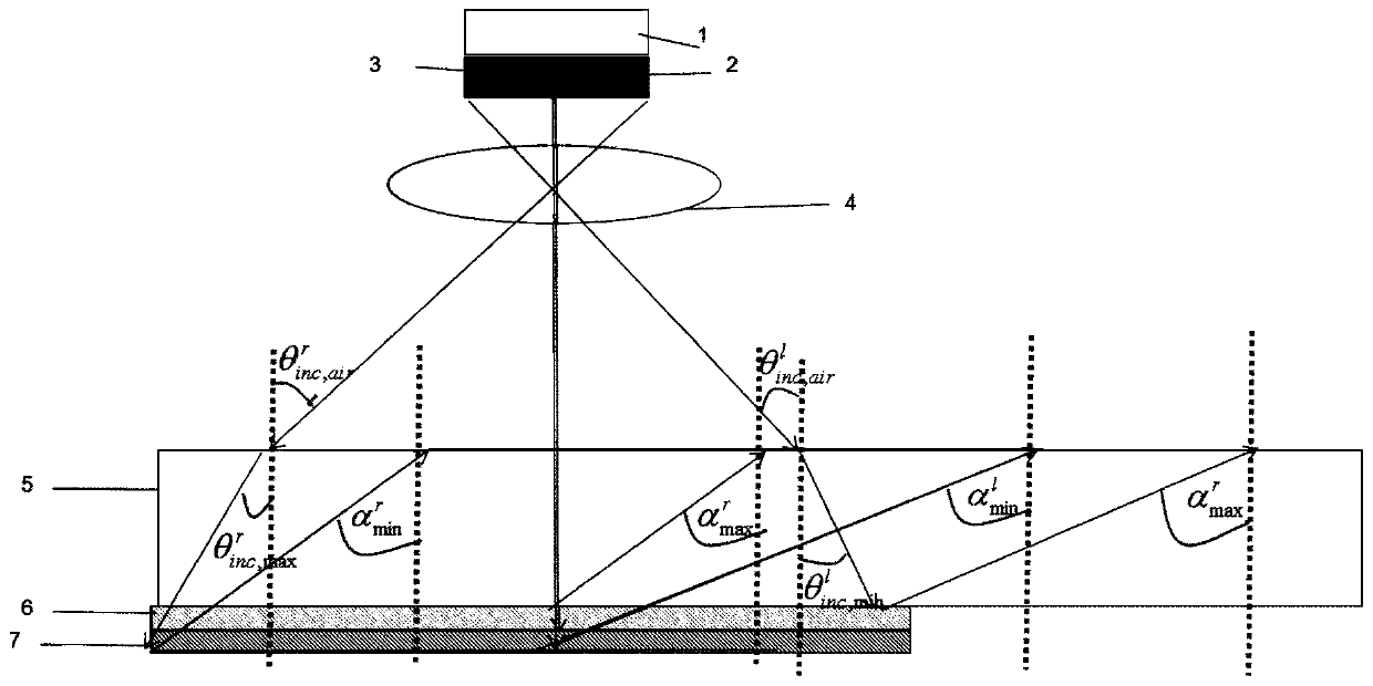
[0023] figure 1 A polarization multiplexing waveguide display device is demonstrated. Depend on figure 1 It can be seen that the image source required by this structure is emitted from the microdisplay 1, and then refracted by the polarization assembly (including the right-handed circular deflector 2 and the left-handed circular deflector 3) and the lens 4 to form a left-handed polarized image and a right-handed polarized image. The left-handed polarization image and the right-handed polarization image are projected onto the in-coupling device, enter the waveguide 5 after Bragg diffraction, and propagate in the waveguide 5 through total internal reflection in the same range of propagation angles until they enter the out-coupling device and occur again Bragg diffraction is diffracted out of the optical waveguide. The in-coupling device is composed of a left-handed circularly polarized light in-coupling grating 6 and a right-handed circularly polarized light in-coupling gratin...

Embodiment 2

[0064] Figure 5 A modified structure for crosstalk is shown. As a preference, in order to avoid possible crosstalk between left-handed circularly polarized light and right-handed circularly polarized light during waveguide propagation, an improved structure is proposed. and figure 1 Compared with the original structure shown in , the right-handed circular polarization component 2 and the left-handed circular polarization component 3 are reduced, and 10 and 11 are added, which are respectively used as 1 / 4 wave plates for generating left-handed circularly polarized light and right-handed circularly polarized light, so that It is guaranteed that the light beam propagating in the waveguide is all linearly polarized light. Unwanted crosstalk can occur.

[0065] As a proof-of-concept demonstration, green light with a wavelength of 550 nm is used as the incident wave, and the refractive index of the waveguide material is n glass = 1.85, therefore, Maximum Spread Angle Selectio...


PUM


Abstract

The invention discloses a polarization multiplexing waveguide display device composed of an in-coupling device, an out-coupling device and a waveguide. By using a color polarizing volume holographic grating as a coupling device of the waveguide, compared with the traditional holographic coupling grating, the novel grating adopts the self-assembly effect and anisotropy of liquid crystals, has highdiffraction efficiency and large diffraction angles, can work at a wide wavelength and angular bandwidth, and has polarization selectivity. In combination with the disclosed double-layer waveguide structure, the invention is applied to near-eye display applications, and can realize color image transmission with large FOV, high transparency and high efficiency.

Description

technical field [0001] The invention relates to a display device using polarization multiplexing waveguide, which is used in AR wearable devices to achieve high-efficiency image transmission and see-through capabilities, and its polarization selectivity enables AR wearable devices to achieve a large field of view horn. Background technique [0002] In recent years, due to its great potential application value in medical treatment, education, games, navigation, etc., AR technology has gained great attention. By transmitting both virtual images and real images to the human eye, AR devices provide an immersive experience to the observer. A key hardware component of AR devices is the optical coupling device, which can couple and transmit virtual and real images to the human eye. [0003] Some light-coupling structures made of reflective or diffractive holographic optical components have been proposed. Among them, the optical diffraction grating is the most common. When appli...

Claims


Application Information

Patent Timeline
IPC IPC(8): G02B6/12G02B6/126G02B6/124G02B27/01
CPCG02B6/12007G02B6/124G02B6/126G02B27/0101
Inventor 张宇宁崔静怡翁一士
Owner SOUTHEAST UNIV
Why Eureka
Try Eureka