
Field channel safety monitoring system

A safety monitoring system, monitoring system technology, applied in the direction of transmission system, closed-circuit television system, TV system components, etc., can solve problems such as broken aircraft engines, safety accidents, slow retrieval speed, etc., to reduce equipment costs and construction costs cost, improve processing efficiency, and reduce flight delays

Inactive Publication Date: 2020-02-25
刘紫云
View PDF4 Cites 5 Cited by
  • Summary
  • Abstract
  • Description
  • Claims
  • Application Information

AI Technical Summary

Problems solved by technology

Moreover, problems such as unclean road surface or damaged road surface, punctured tires, and damaged aircraft engines have always been hidden dangers affecting flight safety.
When the aircraft taxis, takes off or lands on the runway, if the road surface is dirty and there are foreign objects, they may be sucked into the air intake of the aircraft engine by the powerful suction of the aircraft engine, causing damage to the engine blades
Or when an aircraft tire is crushed by a foreign object, it will blow out or deviate from the runway, and the fragments of the blown tire are likely to cause damage to the airframe
These accidents will affect flight safety in light cases, and cause major safety accidents in severe cases.
[0003] At present, in the road safety monitoring system, when the monitoring system detects an abnormality, it is impossible to distinguish whether the abnormality is caused by a non-living body or a living body, and it is impossible to accurately handle accidents, and the processing effect is not good, and If it is necessary to retrieve surveillance video after an accident, it needs to be retrieved from a large number of videos. The accuracy of retrieval is not high, and the retrieval rate is very slow and inefficient.

Method used


Image

  • Field channel safety monitoring system
  • Field channel safety monitoring system
  • Field channel safety monitoring system

Examples


Embodiment Construction

[0027] The following will clearly and completely describe the technical solutions in the embodiments of the present invention with reference to the accompanying drawings in the embodiments of the present invention. Obviously, the described embodiments are only some, not all, embodiments of the present invention. Based on the embodiments of the present invention, all other embodiments obtained by persons of ordinary skill in the art without making creative efforts belong to the protection scope of the present invention.

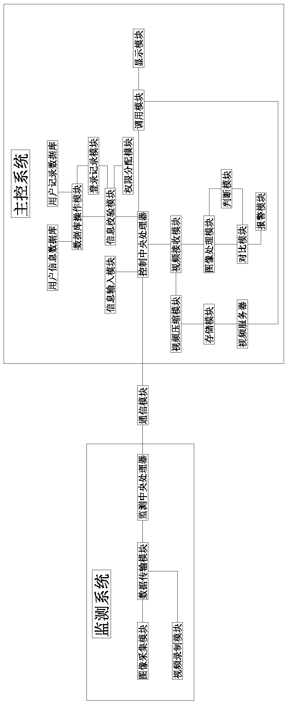
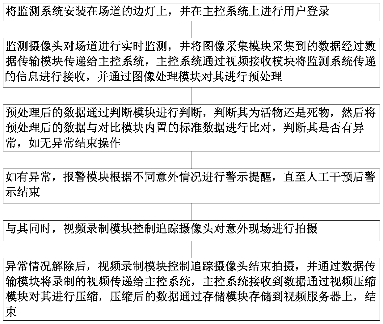
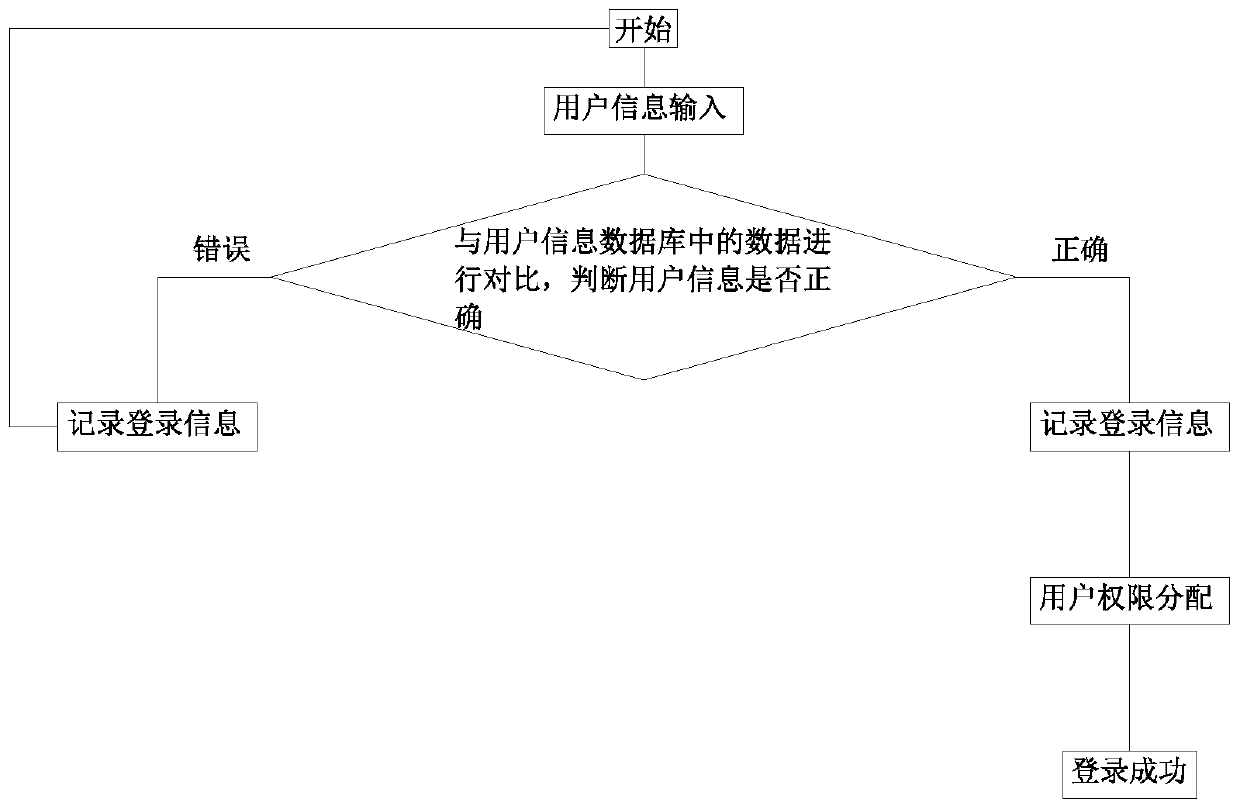
[0028] see Figure 1~4 , in an embodiment of the present invention, a track safety monitoring system includes a monitoring system, a communication module, a main control system and side lights, the monitoring system performs data interaction with the main control system through the communication module, and the monitoring system includes an image acquisition module, a data Transmission module, monitoring CPU and video recording module, the image acquisition mo...


PUM


Abstract

The invention discloses a field channel safety monitoring system, which comprises a monitoring system, a communication module, a main control system and side lamps, and is characterized in that the monitoring system performs data interaction with the main control system through the communication module, and the monitoring system comprises an image acquisition module, a data transmission module, amonitoring central processing unit and a video recording module. The ringtone alarm module, the voice alarm module, the alarm branch module, the comparison module and the judgment module are matched for use. Whether an accident scene is triggered by a non-life body or a life body can be accurately judged so as to judge whether the field road surface is damaged or not, whether foreign objects existon the field road surface or not, whether individual lamplight faults exist or not and whether bird situations exist in the air of a field area or not , and different processing personnel are dispatched according to different alarm sounds. Therefore, accidents can be accurately handled, the handling efficiency is improved, the handling effect is good, and the aviation safety is improved.

Description

technical field [0001] The invention relates to the technical field of electronic equipment, in particular to a track safety monitoring system. Background technique [0002] Airports, also known as airports and airports, are more formally known as airports. Airports have different sizes. In addition to runways, airports usually also have towers, aprons, air passenger terminals, maintenance plants and other facilities, and provide airport control services, air traffic control and other services. Field road generally refers to the airport pavement. The airport pavement refers to one or more layers of artificial structures paved with road construction materials on the natural soil foundation and the top surface of the base layer. It is used for aircraft take-off, landing, taxiing and maintenance. 1. Parking aprons, such as runways, taxiways, passenger aprons, maintenance aprons, cargo aircraft aprons, parking aprons, etc. In the field of aviation, track safety is a safety iss...

Claims


Application Information

Patent Timeline
Patent Type & Authority Applications(China)
IPC IPC(8): H04N7/18H04N5/76H04L29/08
CPCH04L67/06H04N5/76H04N7/18H04N7/188
Inventor 刘紫云许杏海
Owner 刘紫云
Learn More