Production device of hinge shafts

A production device and hinge shaft technology, which is applied to other manufacturing equipment/tools, manufacturing tools, etc., can solve the problems of high labor intensity and affecting production efficiency, so as to improve drilling efficiency, reduce labor intensity and ensure stability Effect

Active Publication Date: 2020-02-28
山东建桥机械股份有限公司
View PDF12 Cites 3 Cited by
  • Summary
  • Abstract
  • Description
  • Claims
  • Application Information

AI Technical Summary

Problems solved by technology

[0006] The above-mentioned existing technical solutions have the following defects: after the shot blasting machine processes the hinge shaft, it needs to pour the processed hinge shaft into the holding frame, and then the staff transports the holding frame to the drilling devic

Method used


Image

  • Production device of hinge shafts
  • Production device of hinge shafts
  • Production device of hinge shafts

Examples


Embodiment 2

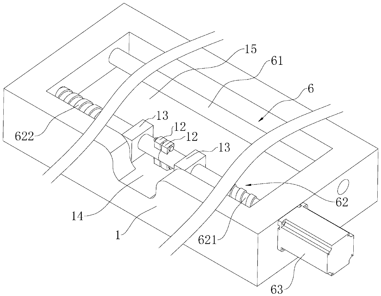
[0048] Embodiment 2: The difference with Embodiment 1 is that, with reference to figure 2 , the above-mentioned threaded rod one 621 and the adjacent end of the threaded rod two 622 are separated, and the outer walls of the threaded rod one 621 and the threaded rod two 622 adjacent ends are respectively provided with two sets of corresponding limit blocks 12, and the two sets of limit blocks 12 is evenly arranged along the threaded rod one 621 / threaded rod two 622 circumferential direction; two sets of limit blocks 12 are provided with corresponding through holes, and the same bolt is inserted in the through holes of the same set of limit blocks 12, and one end of the bolt is connected to the nut The threads are matched to realize the coaxial connection or separation of the first threaded rod 621 and the second threaded rod 622.

[0049] In this embodiment, the chute 15 is located below the mounting seat 231 and two positioning seats 13 are fixed, and one end of the threaded ...


PUM


Abstract

The invention relates to a production device of hinge shafts. The production device comprises a shot blasting machine and a drilling device. The drilling device comprises a machine base, a drilling mechanism arranged on the machine base and an installation mechanism used for installing the hinge shafts. The installation mechanism comprises an installation base perpendicularly arranged on the machine base, a three-jaw chuck arranged on the installation base and a regulation mechanism driving the three-jaw chuck to move linearly. A conveyor is arranged at the opening end of a shot blasting chamber of the shot blasting machine. The conveyor comprises machine frames, rotation rollers evenly arranged in the length direction of the machine frames and connected to the two sides of the machine frames in a rotating manner, a belt wound on the rotation rollers and a first motor driving the rotation rollers to rotate. The upper end of the belt is higher than the upper end of the three-jaw chuck.The three-jaw chuck and the belt are located on the same straight line in the linear movement process. The gap between the machine frames is not smaller than the outer diameters of the hinge shafts. The production device has the effects of lowering the labor intensity of workers and ensuring the production efficiency.

Description

technical field [0001] The invention relates to the technical field of oil cylinder hinge shaft processing, in particular to a hinge shaft production device. Background technique [0002] At present, the hydraulic cylinder is a linear motion actuator whose output force is proportional to the effective area of ​​the piston and the pressure difference on both sides. A hydraulic cylinder is generally composed of a cylinder, a cylinder head, a piston, a piston rod, a sealing device, a buffer device and an exhaust device, which drive the piston rod to drive the piston to complete the linear reciprocating motion; during the use of the hydraulic cylinder, many applicable environments require The hydraulic cylinder can be tilted at a certain angle, so a hinge shaft is generally provided on the outer wall of the cylinder barrel, and the hinge shaft is used to connect the hydraulic cylinder with the external features to realize the change of the tilt angle of the hydraulic cylinder. ...

Claims


Application Information

Patent Timeline
IPC IPC(8): B23P23/04
CPCB23P23/04
Inventor 刘衍巧张方军田其伟刘恩奎
Owner 山东建桥机械股份有限公司
Why Eureka
Try Eureka