
Vertical dehydration device for biogas purification

A dehydration device, biogas technology, applied in gas fuel, petroleum industry, fuel and other directions, can solve the problems of corrosion and desulfurization equipment, water can not be completely condensed and separated, and not have it, so as to increase the number of collisions, facilitate the maintenance of equipment, and avoid structural problems. single effect

Inactive Publication Date: 2020-02-28
GUANGDONG UNIV OF PETROCHEMICAL TECH
View PDF4 Cites 0 Cited by
  • Summary
  • Abstract
  • Description
  • Claims
  • Application Information

AI Technical Summary

Problems solved by technology

[0003] The main component of biogas is methane, and it also contains a large amount of water and hydrogen sulfide. After successful biogas fermentation, the water in the biogas must be separated first, and then dry desulfurization is carried out. The poor effect of water separation will not only affect The effect and efficiency of dry desulfurization will also corrode the desulfurization equipment and shorten the service life of the desulfurization equipment, so the dehydration of biogas is very important
[0004] The existing biogas dehydration device has the following defects: 1) the use of chemical agents for water absorption is high in cost, easy to cause secondary pollution, and high in energy consumption; There is a temperature gradient, so that the moisture inside the biogas cannot be completely condensed and separated; 3) When dehydrating biogas, the structure and method are single, and it does not have the effect of alternating the two dehydration methods, thereby reducing the dehydration efficiency

Method used


Image

  • Vertical dehydration device for biogas purification
  • Vertical dehydration device for biogas purification
  • Vertical dehydration device for biogas purification

Examples


Embodiment 1

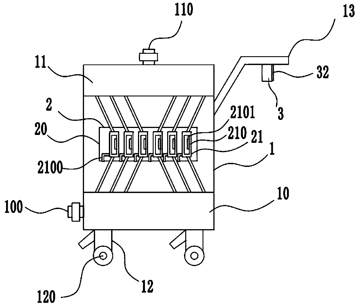
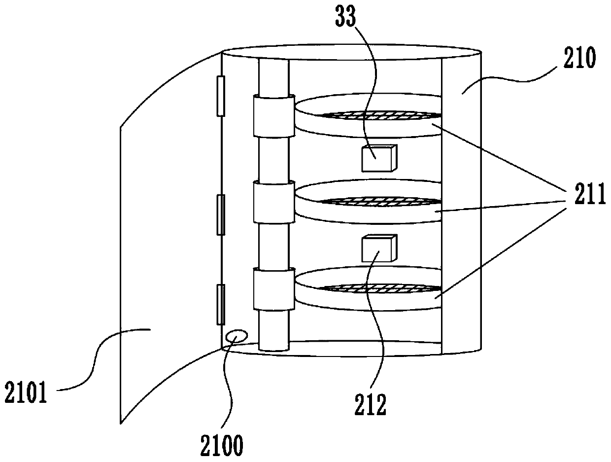
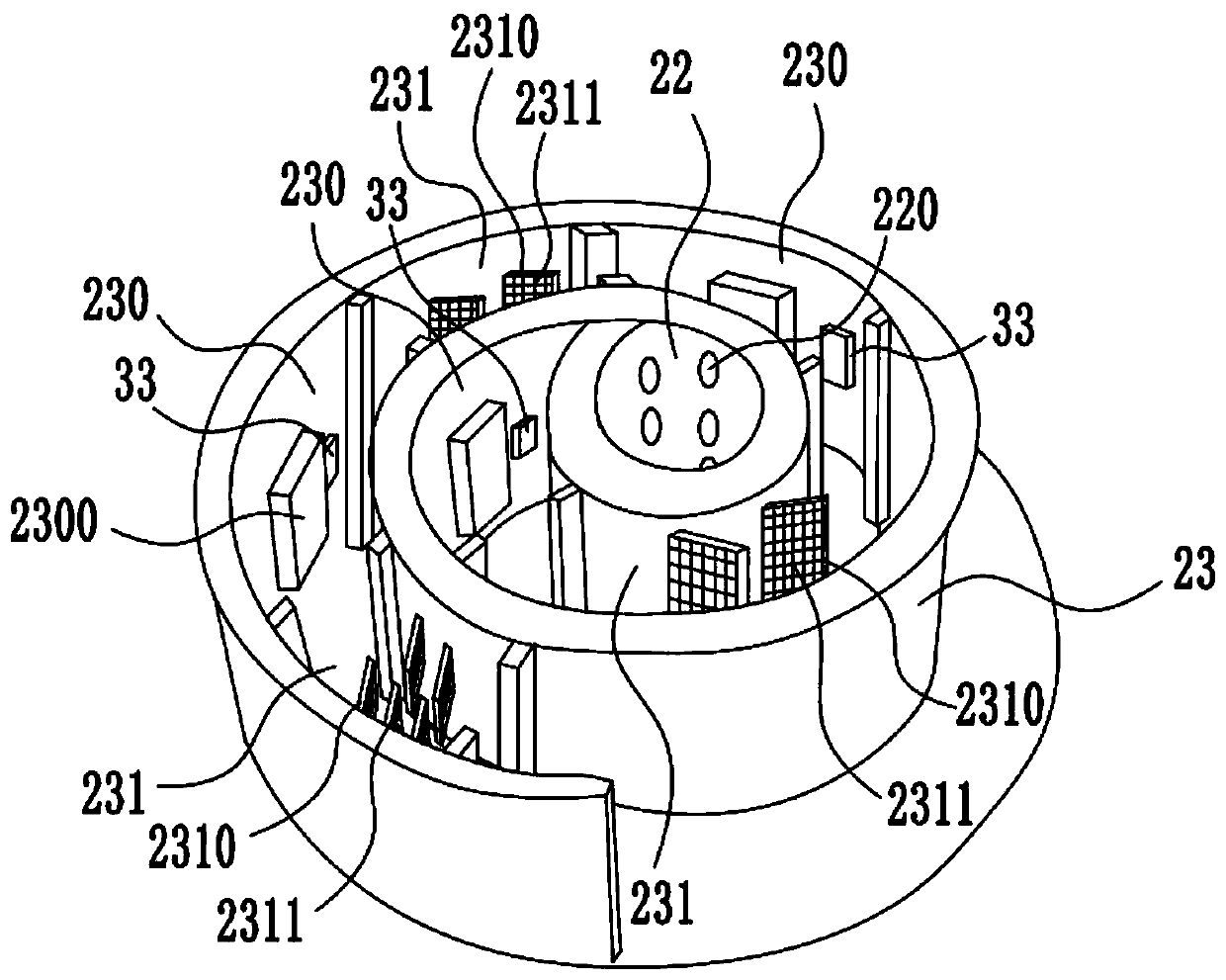
[0029] Such as figure 1 The shown vertical dehydration device for biogas purification and purification mainly includes a vertical frame body 1 with a biogas splitter box 10 at the bottom end and a biogas temporary storage box 11 at the upper end, and is arranged in the middle of the vertical frame body 1 and A biogas purification and dehydration element 2 for dehydrating biogas, an intelligent control element 3, and a power supply; a biogas inlet 100 is provided on the side wall of the biogas distribution box 10, and a biogas outlet 110 is provided at the upper end of the biogas temporary storage box 11, and the biogas inlet 100 and the biogas outlet Electromagnetic valves are provided at 110 places, and there are legs 12 at the bottom end of the vertical frame body 1. The bottom end of the legs 12 is provided with a moving wheel 120, and the moving wheel 120 is provided with a brake element. One side of the vertical frame body 1 is provided with a push handle 13, Through the ...

Embodiment 2

[0037] Such as figure 1 The shown vertical dehydration device for biogas purification and purification mainly includes a vertical frame body 1 with a biogas splitter box 10 at the bottom end and a biogas temporary storage box 11 at the upper end, and is arranged in the middle of the vertical frame body 1 and A biogas purification and dehydration element 2 for dehydrating biogas, an intelligent control element 3, and a power supply; a biogas inlet 100 is provided on the side wall of the biogas distribution box 10, and a biogas outlet 110 is provided at the upper end of the biogas temporary storage box 11, and the biogas inlet 100 and the biogas outlet Electromagnetic valves are provided at 110 places, and there are legs 12 at the bottom end of the vertical frame body 1. The bottom end of the legs 12 is provided with a moving wheel 120, and the moving wheel 120 is provided with a brake element. One side of the vertical frame body 1 is provided with a push handle 13, Through the ...

Embodiment 3

[0045] Such as figure 1 The shown vertical dehydration device for biogas purification and purification mainly includes a vertical frame body 1 with a biogas splitter box 10 at the bottom end and a biogas temporary storage box 11 at the upper end, and is arranged in the middle of the vertical frame body 1 and A biogas purification and dehydration element 2 for dehydrating biogas, an intelligent control element 3, and a power supply; a biogas inlet 100 is provided on the side wall of the biogas distribution box 10, and a biogas outlet 110 is provided at the upper end of the biogas temporary storage box 11, and the biogas inlet 100 and the biogas outlet Electromagnetic valves are provided at 110 places, and there are legs 12 at the bottom end of the vertical frame body 1. The bottom end of the legs 12 is provided with a moving wheel 120, and the moving wheel 120 is provided with a brake element. One side of the vertical frame body 1 is provided with a push handle 13, Through the ...


PUM


Abstract

The invention discloses a vertical dehydration device for biogas purification, and belongs to the technical field of biogas purification. The device mainly comprises a vertical frame body, biogas purification and dehydration elements, an intelligent control element and a power supply, the biogas purification and dehydration elements of three different structures are arranged to dehydrate biogas, each structure can dehydrate the biogas in multiple layers, the defects that a traditional biogas dehydration treatment device is single in structure, poor in dehydration effect and poor in practicability are overcome, the number of collisions between the biogas and the biogas purification and dehydration elements is increased, so that moisture in the biogas can be better and completely removed, and the dehydration effect is increased; by controlling the gradient of the condensation temperature of the biogas purification and dehydration elements to reduce, the moisture in the biogas can be completely condensed and desulfurized, so that the dehydration effect is ensured, and the use requirement is met; The vertical dehydration device has the advantages of good dehydration effect, high reliability and strong practicability, and is suitable for mass promotion.

Description

technical field [0001] The invention relates to the technical field of biogas purification, in particular to a vertical dehydration device for biogas purification and purification. Background technique [0002] Biogas is a mixed gas produced by the fermentation of microorganisms under anaerobic conditions. Biogas, as the name implies, is the gas in swamps. People often see that there are bubbles in swamps, sewers or cesspools. Come out, if we strike a match, we can ignite it, this is the naturally occurring biogas, because this gas was first found in the swamp, so it is called biogas, human and animal manure, straw, sewage and other organic matter In a closed biogas digester, it is fermented under anaerobic (no oxygen) conditions, and is decomposed and transformed by a variety of biogas fermentation microorganisms to produce biogas. [0003] The main component of biogas is methane, and it also contains a large amount of water and hydrogen sulfide. After successful biogas fe...

Claims


Application Information

Patent Timeline
Patent Type & Authority Applications(China)
IPC IPC(8): C10L3/10
CPCC10L3/106
Inventor 牛晓君郑小贤林璋郭华芳彭绍洪刘洋涂宁宇余成华王雅婷李霞钟华文
Owner GUANGDONG UNIV OF PETROCHEMICAL TECH
Learn More