
An underwater power generation device based on the principle of worm drive

A technology of worm drive and power generation device, which is applied in the field of electric power, can solve problems affecting the balance of the underwater ecological system, damage to the thrust surface of the seal, and stop working of the power generation device, so as to shorten maintenance intervals, increase efficiency, and improve power generation efficiency. Effect

Active Publication Date: 2021-06-04
山东同其智能科技有限公司
View PDF7 Cites 0 Cited by
  • Summary
  • Abstract
  • Description
  • Claims
  • Application Information

AI Technical Summary

Problems solved by technology

[0003] The existing kinetic energy hydropower usually uses the fan blades to rotate with the water flow underwater to drive the internal rotor to rotate to generate electricity. However, when the fan blades rotate, they will often cause damage to fish schools at the bottom of the water and affect the balance of the underwater ecosystem. When the fan blade rotates, it is very easy to entangle the aquatic plants on the bottom of the water, causing the impeller to be stuck, which will cause the power generation device to stop working and affect the efficiency of power generation. In addition, the existing underwater power generation devices hope to be as 100% sealed as possible. Sealing is therefore usually only possible with high contact forces, which in turn lead to high friction and thus high wear, which shortens maintenance intervals and shortens the operating life, where the thrust of the seal is often also reduced The surface is damaged, so the maintenance work is not limited to the replacement of the seal, and even the entire facility needs to be replaced, which increases the economic loss

Method used


Image

  • An underwater power generation device based on the principle of worm drive
  • An underwater power generation device based on the principle of worm drive
  • An underwater power generation device based on the principle of worm drive

Examples


Embodiment Construction

[0028] The following will clearly and completely describe the technical solutions in the embodiments of the present invention with reference to the accompanying drawings in the embodiments of the present invention. Obviously, the described embodiments are only some, not all, embodiments of the present invention. Based on the embodiments of the present invention, all other embodiments obtained by persons of ordinary skill in the art without making creative efforts belong to the protection scope of the present invention.

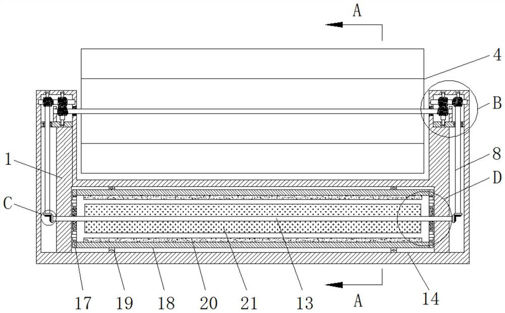
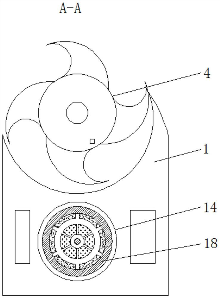
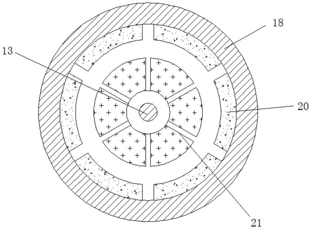
[0029] see Figure 1-7 , an underwater power generation device based on the principle of worm drive, including a housing 1, a sealing chamber 2, a rotating shaft 3, a turbine 4, a first sealing ring 5, a first worm 6, a second worm 7, a connecting rod 8, and a sealing plate 9. The second sealing ring 10, the first bevel gear 11, the second bevel gear 12, the connecting shaft 13, the power generation chamber 14, the central tooth 15, the planetary gear 16, the ...


PUM


Abstract

The invention relates to the field of electric power technology, and discloses an underwater power generation device based on the principle of worm drive, which includes a casing, the top of the casing is fixedly connected with a sealed cavity, and the inside of the sealed cavity is movably connected with a rotating shaft. A turbine is fixedly connected to the outside of the rotating shaft, a first seal ring is movably connected to the outside of the rotating shaft, a first worm is connected to the outside of the rotating shaft, and a second worm is connected to the outside of the first worm. In use, since the turbine is a horizontal impeller and rotates horizontally in the housing, when the turbine rotates, the turbine will not damage the passing fish at the bottom of the water under the rotation of the water flow, protect the ecological environment at the bottom of the water, and avoid damage to the ecological environment at the bottom of the water. At the same time, it can effectively prevent the underwater plants from wrapping around the turbine, which will cause the turbine to be entangled, and the underwater power generation device will stop working, so as to ensure the normal operation of kinetic hydropower generation and improve the power generation efficiency of underwater power generation.

Description

technical field [0001] The invention relates to the field of electric power technology, in particular to an underwater power generation device based on the principle of worm drive. Background technique [0002] Traditional hydropower requires the construction of dams—this kind of large-scale construction projects often changes the local landscape and ecosystems, causing serious impacts on the local ecosystems. Scientists have proposed an ideal solution: kinetic hydropower, namely The natural flow of rivers and tides is used as power to generate electricity through underwater turbines. [0003] The existing kinetic energy hydropower usually uses the fan blades to rotate with the water flow underwater to drive the internal rotor to rotate to generate electricity. However, when the fan blades rotate, they will often cause damage to fish schools at the bottom of the water and affect the balance of the underwater ecosystem. When the fan blade rotates, it is very easy to entangle...

Claims


Application Information

Patent Timeline
Patent Type & Authority Patents(China)
IPC IPC(8): F03B13/10F03B3/12F03B11/00F16H37/04H02K7/116
CPCF03B3/12F03B11/002F03B11/006F03B13/10F16H37/041F16H37/046H02K7/116Y02E10/20
Inventor 李五洲
Owner 山东同其智能科技有限公司
Learn More