Coupling fiber manufacturing method and assembly clamp

A technology for assembling a fixture and a manufacturing method, which is applied to the coupling of optical waveguides, light guides, optics, etc., can solve the problems of easily burning optical fibers, reducing power, affecting coupling efficiency, etc., so as to improve coupling efficiency, ensure mechanical tension, and be difficult to absorb heat. Effect

Inactive Publication Date: 2020-02-28
Shandong Huaguang Optoelectronics Co. Ltd.
View PDF11 Cites 5 Cited by
  • Summary
  • Abstract
  • Description
  • Claims
  • Application Information

AI Technical Summary

Problems solved by technology

The third is that only the side of the through hole can be irradiated by ultraviolet light after filling the glue, and the front and rear end ultraviolet light itself cannot be completely transmitted, resulting in insufficient curing
Fourth, insufficiently filled fiber end faces cannot obtain good end face quality, which affects coupling efficiency
Fifth, too much glue is filled, it is easy to absorb heat under high power, and the optical fiber is affected by stress, which easily leads to power reduction
[0008] as attached figure 1 And attached figure 2 As shown, in the traditional laser coupling structure, when the optical fiber is inserted into the ceramic ferrule, the glue is squeezed upwards to form an overflow glue layer 5 outside the ferrule seat, which is easy to burn the optical fiber

Method used


Image

  • Coupling fiber manufacturing method and assembly clamp
  • Coupling fiber manufacturing method and assembly clamp
  • Coupling fiber manufacturing method and assembly clamp

Examples


Embodiment 1

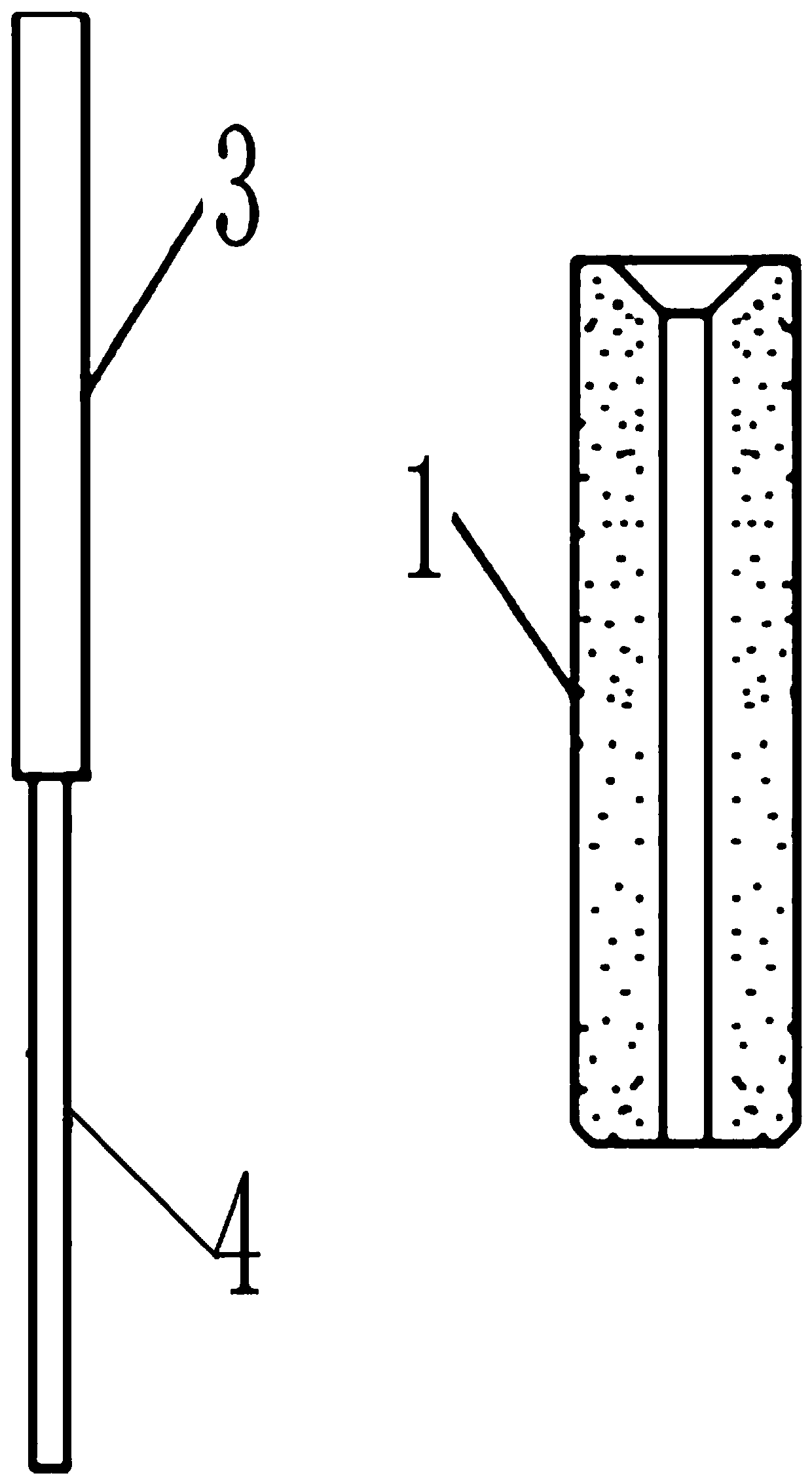
[0051] A step of grinding the bare end 4 after step a) is also included. Grinding the exposed end 4 can ensure the smoothness of its surface, which is beneficial to improve its transmission rate of optical signals.

Embodiment 2

[0053] It also includes the step of inspecting the coating on the surface of the exposed end 4 after step a). Before curing the optical fiber 3 and the ferrule holder 2, it is checked whether the coating of the optical fiber bare end 4 is damaged, so as to ensure the quality of the coupled optical fiber.

Embodiment 3

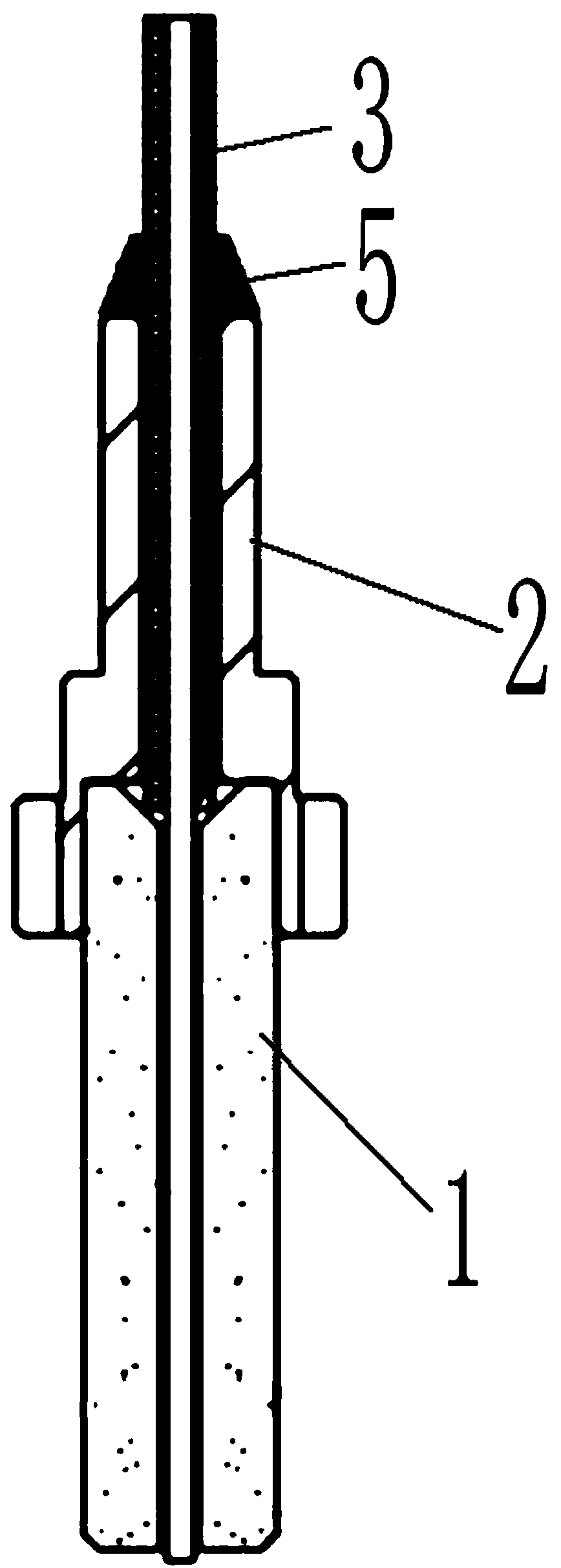
[0055] The glue-coated area in step b) is 1 / 2 area of ​​the whole exposed end 4 upward from the center point of the exposed end 4 . Setting 1 / 2 area for glue coating can satisfy the fixing firmness of the bare fiber end 4 and the ferrule seat 2, so that it can meet the requirements of mechanical tension, and can prevent overflow caused by excessive glue.


PUM


Abstract

The invention relates to a coupling optical fiber manufacturing method and an assembling clamp. An optical fiber is peeled off to form the exposed end, part of the exposed end is coated with glue, theglue amount and the filling quality of the glue are controlled more effectively, and the situation that in a traditional coupling process, the end of an inserting core base has an overflowing glue layer is avoided. Only the tail end part of a ceramic ferrule is filled and fixed by the ultraviolet glue, so that the exposed end of the optical fiber is effectively protected while the mechanical tension is ensured. Since the bottom of the ceramic ferrule at the lower end of the exposed end is protruded by 1-10 cm, a non-standard ceramic ferrule or a non-standard ferrule with a copper base can beused, the protruding part is bare without glue and is in a free state, and light transmission is facilitated. A high-temperature-resistant protective sleeve only makes contact and is fixed to a ferrule seat, heat tends not to be absorbed, and temperature of a laser tube shell and nozzle can be reduced. The coupling efficiency of the optical fiber and a semiconductor laser is improved, and heat dissipation is sound. Risks of optical fiber burnout and high temperature are avoided to a certain extent.

Description

technical field [0001] The invention relates to the technical field of semiconductor laser coupling, in particular to a coupling optical fiber manufacturing method and an assembly fixture. Background technique [0002] Due to the advantages of small size, light weight, high conversion efficiency, long service life, and direct internal modulation, semiconductor lasers are widely used in medical, display, pumping, industrial processing and other fields, such as optical fiber communication, laser ranging, target Instructions, laser guidance, laser radar, space optical communication, etc. [0003] The combination of optical fibers and semiconductor lasers has made semiconductor lasers more widely used. For example, in the field of communication, how to make the output light of lasers more stable and transmit longer distances, and how to make the output of semiconductor lasers in pumping solid-state lasers Optical power can be more effectively transmitted to the laser gain mediu...

Claims


Application Information

Patent Timeline
Patent Type & Authority Applications(China)
IPC IPC(8): G02B6/42G02B6/245
CPCG02B6/245G02B6/4202G02B6/4239G02B6/4268
Inventor 余兴社刘成成邵慧慧开北超
Owner Shandong Huaguang Optoelectronics Co. Ltd.
Why Eureka
Try Eureka