Excitation fuse integrated with arc extinguishing melt

A fuse and melt technology, used in emergency protection devices, circuits, electrical components, etc., can solve the problems that the fuse protection time cannot meet the requirements, cannot meet the short-term overshoot of the current, and the battery pack heats up and catches fire and burns. It has the advantages of price and volume, mature production technology and strong resistance to current impact.

Pending Publication Date: 2020-02-28
XIAN ZHONGRONG ELECTRIC CO LTD
View PDF0 Cites 7 Cited by
  • Summary
  • Abstract
  • Description
  • Claims
  • Application Information

AI Technical Summary

Problems solved by technology

For example, in the case of new energy car main circuit protection, if the load has a low multiple overload or short circuit, the use of a fuse with a low current specification cannot meet the short-term overshoot of the current, and if the fuse with a high current specification cannot meet the requirements of fast protection Require
In the current lithium battery pack that provides energy for new energy vehicles, the output current is about several times the rated current in the event of a short circuit, and the protection time of the fuse cannot meet the requirements, causing the battery pack to heat up and burn.
Due to the heating of the withstand current and the heating and melting of the breaking current, both originate from the current flowing through the fuse. This kind of protective device that uses current heating and fusing cannot withstand a relatively large rated current or withstand a strong short-term overload / impact current. (For example, the short-term high current when the electric vehicle starts or climbs a slope), the breaking speed of a fault current with a certain amplitude is fast enough, or the protection speed of a fault current with a certain amplitude is fast enough to achieve a higher rating current, or withstand large overload / inrush current without damage
[0003] Another problem with thermal fuses is that they cannot communicate with external devices and cannot be triggered by signals other than current, such as vehicle ECU, BMS or other sensors, etc.
However, there are still some deficiencies and defects in it, which lead to limited arc extinguishing ability: limited by air, it is difficult to break a large fault current; the arc is directly cooled by air, and the breaking capacity is greatly affected by air pressure and temperature and humidity; during the breaking process, The arc directly burns the piston knife, and the combustion of the piston knife will affect the smooth extinguishing of the arc; during the breaking process, there is no other structure or mechanism to assist arc extinguishing except for the limited disturbance of the arc by the piston knife

Method used


Image

  • Excitation fuse integrated with arc extinguishing melt
  • Excitation fuse integrated with arc extinguishing melt
  • Excitation fuse integrated with arc extinguishing melt

Examples


Embodiment Construction

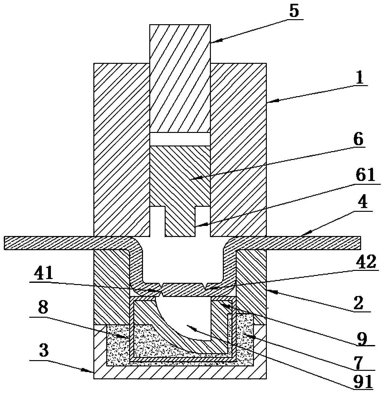
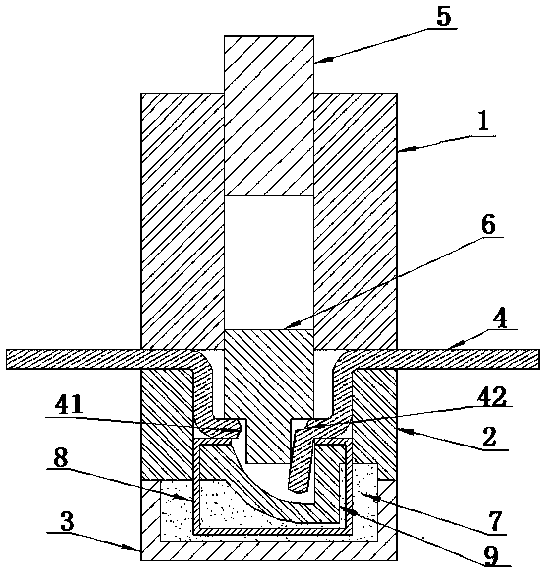
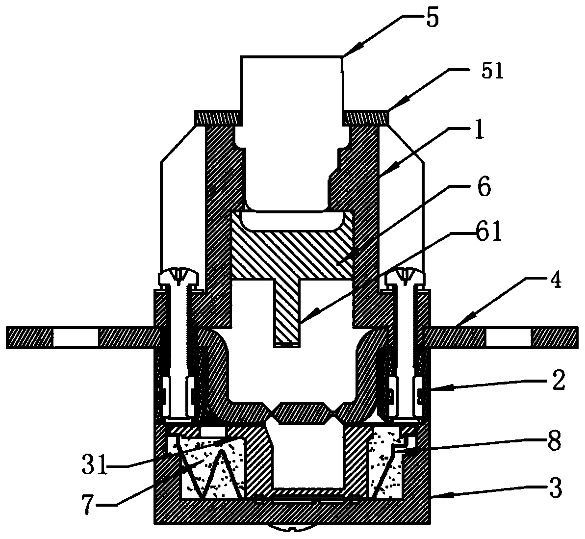
[0024] With regard to the above technical solutions, embodiments are given and described in detail in combination with figures. The fast current cut-off device of the present invention mainly includes an upper casing, a conductive plate, a middle casing, a lower casing, a gas generating device, etc., see Figure 1 to Figure 2 ,in.

[0025] The shell, in this embodiment, is composed of an upper shell 1 , a middle shell 2 , and a bottom shell 3 . A conductive plate 4 is arranged between the contact surface of the upper shell and the middle shell, and the upper shell, the middle shell and the conductive plate are fixed together by screws between the upper shell and the middle shell. The upper shell, the middle shell and the bottom shell are fixed together by screws to become the outer shell of the excitation fuse. The contact parts between the conductive plate and the upper shell and the end faces of the middle shell are sealed.

[0026] An accommodating cavity is opened in th...


PUM


Abstract

An excitation fuse integrated with an arc extinguishing melt comprises an upper shell and a lower shell which are successively arranged from top to bottom. A conductive plate is arranged between the upper shell and the lower shell. An accommodating cavity with a downward opening is arranged in the upper shell, and the accommodating cavity with an upward opening is arranged in the lower shell. An ignition explosion device and a piston are successively arranged in the accommodating cavity of the upper shell from top to bottom. The accommodating cavity of the lower shell is filled with an arc extinguishing medium. A sealing element for sealing the arc extinguishing medium is arranged in the accommodating cavity of the lower shell. The sealing element is provided with the accommodating cavitywhich is provided with the upward opening and is used for making the conductive plate fall off after disconnection. The melt is arranged in the arc extinguishing medium, and two ends of the melt passthrough the upper end surface of the lower shell and are connected with a bottom of the conductive plate in parallel. A disconnected part of the conductive plate after being impacted and disconnectedby the piston is located between connection parts of the two ends of the melt and the conductive plate. The fuse has advantages that influences of air pressure, temperature and humidity on the fuse are small, reliable breaking can be achieved under various working conditions, and a breaking capacity is high.

Description

technical field [0001] The invention relates to the fields of power control and electric vehicles, in particular to an auxiliary arc-extinguishing structure for controlling and cutting off an excitation fuse of a current transmission circuit through an external signal. Background technique [0002] The product of circuit overcurrent protection is a fuse that is blown based on the heat generated by the current flowing through the fuse. The main problem is the matching relationship between the thermal fuse and the load. For example, in the case of new energy car main circuit protection, if the load has a low multiple overload or short circuit, the use of a fuse with a low current specification cannot meet the short-term overshoot of the current, and if the fuse with a high current specification cannot meet the requirements of fast protection Require. In the current lithium battery pack that provides energy for new energy vehicles, the output current is about several times the...

Claims


Application Information

Patent Timeline
Patent Type & Authority Applications(China)
IPC IPC(8): H01H85/38H01H85/165
CPCH01H85/165H01H85/38
Inventor 段少波戈西斌石晓光王伟王宁
Owner XIAN ZHONGRONG ELECTRIC CO LTD
Why Eureka
Try Eureka