Clock circuit and clock signal generation method
A clock circuit and clock signal technology, applied in the direction of electrical components, automatic power control, etc., can solve the problem of not being able to provide high-speed, wide-frequency clock signals, etc.
- Summary
- Abstract
- Description
- Claims
- Application Information
AI Technical Summary
Problems solved by technology
Method used
Image

Examples
Embodiment 1
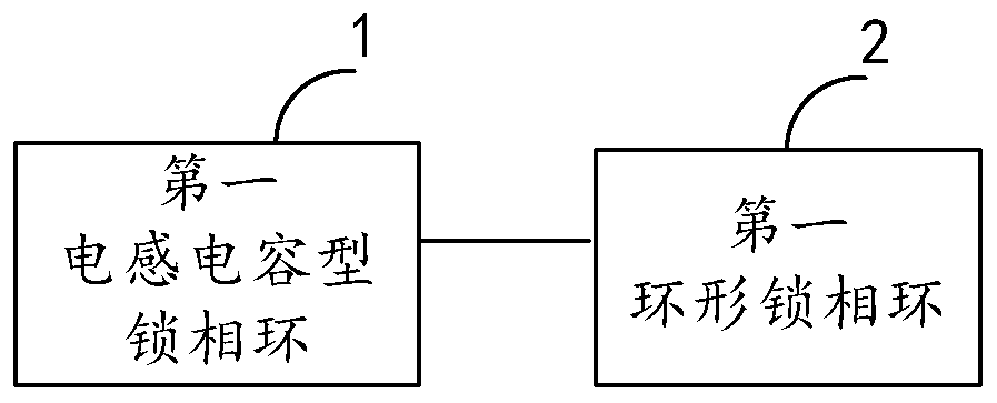
[0065] like figure 1 As shown, this embodiment provides a clock circuit, including:
[0066] The first inductance-capacitance phase-locked loop 1 (LC-PLL, Inductor Capacitor-PhaseLocked Loop) and the first ring-shaped phase-locked loop 2 (Ring-PLL, Ring-Phase Locked Loop) cascaded in sequence;
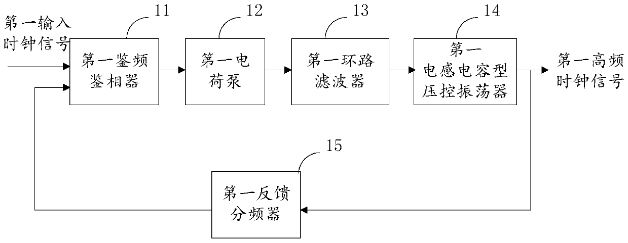
[0067] The first inductance-capacitance phase-locked loop 1 is used to perform frequency multiplication processing on the first input clock signal to generate a first high-frequency clock signal;
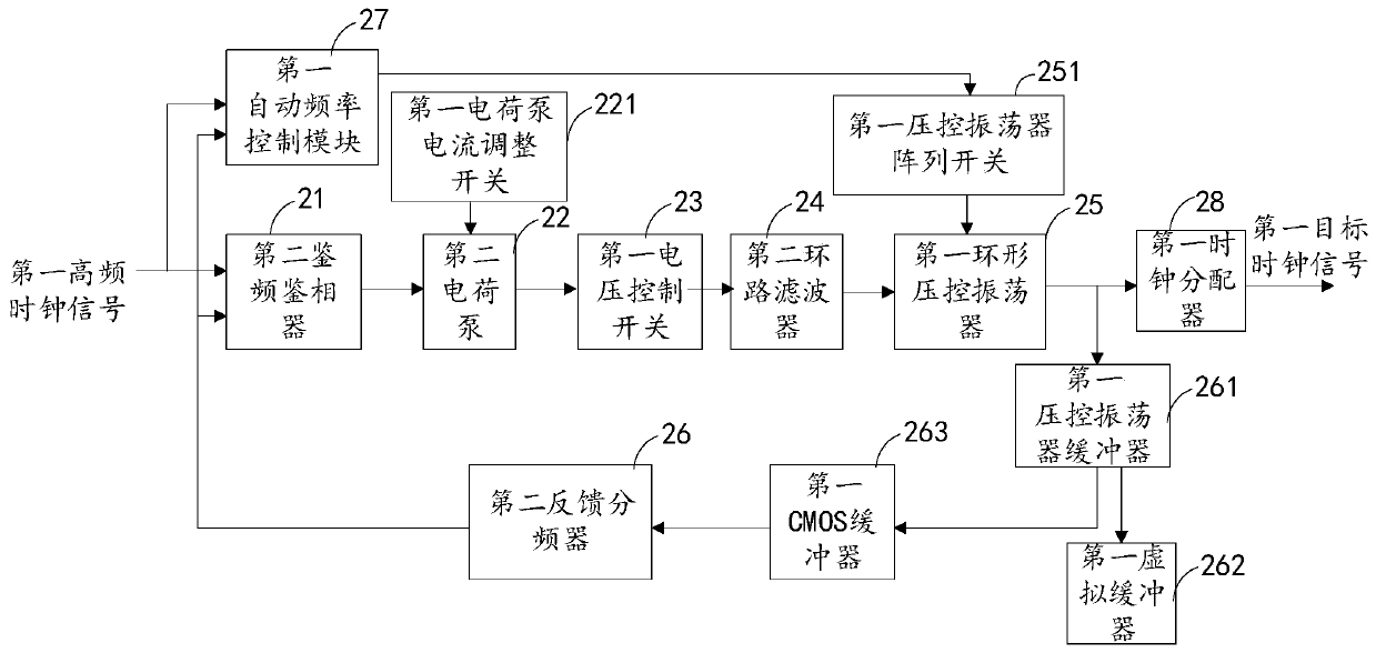
[0068] The first annular phase-locked loop 2 performs frequency multiplication processing on the first high-frequency clock signal based on a frequency configuration coefficient to generate a first target clock signal, and the frequency configuration coefficient is used to configure the first target clock signal Frequency of.
[0069]It should be noted that the first high-frequency clock signal provided by the first inductance-capacitance phase-locked loop 1 is a high-frequency clock signa...
Embodiment 2
[0099] like Figure 4 As shown, this embodiment provides a clock circuit, including:
[0100] A second inductance-capacitance phase-locked loop 3, a frequency divider 5 and a second annular phase-locked loop 4 cascaded in sequence;
[0101]The second inductance-capacitance phase-locked loop 3 is used to perform frequency multiplication processing on the second input clock signal to generate a second high-frequency clock signal;
[0102] The frequency divider 5 is used to perform frequency division processing on the second high-frequency clock signal to generate a third high-frequency clock signal;
[0103] The second annular phase-locked loop 4 performs frequency multiplication processing on the third high-frequency clock signal based on a frequency configuration coefficient to generate a second target clock signal, and the frequency configuration coefficient is used to configure the second target clock signal Frequency of.
[0104] As an optional embodiment, the frequency ...
Embodiment 3
[0144] like Figure 12 As shown, this embodiment provides a method for generating a clock signal, including:
[0145] Step S101: receiving the first input clock signal by the first inductance-capacitance phase-locked loop, and performing frequency multiplication processing on the first input clock signal to generate a first high-frequency clock signal;
[0146] Step S102: Perform frequency multiplication processing on the first high-frequency clock signal by the first annular phase-locked loop to generate a first target clock signal.
[0147] It should be noted that the first high-frequency clock signal generated by the first LC-type phase-locked loop is a high-frequency clock signal, and this high-frequency clock signal has the advantages of high frequency and low jitter (that is, good phase noise characteristics). The bandwidth of the first annular phase-locked loop is adjusted based on the frequency of the first high-frequency clock signal output by the first inductance-ca...
PUM
 Abstract
Description
Claims
Application Information
 - R&D
- Intellectual Property
- Life Sciences
- Materials
- Tech Scout
- Unparalleled Data Quality
- Higher Quality Content
- 60% Fewer Hallucinations
Browse by: Latest US Patents, China's latest patents, Technical Efficacy Thesaurus, Application Domain, Technology Topic, Popular Technical Reports.
© 2025 PatSnap. All rights reserved.Legal|Privacy policy|Modern Slavery Act Transparency Statement|Sitemap|About US| Contact US: help@patsnap.com