Centrifugal separation and recycling device

A recovery device and centrifugal separation technology, applied in the field of centrifugal separation and recovery devices, can solve the problems of secondary pollution treatment costs, inadequate treatment, etc.

Inactive Publication Date: 2020-03-06
江苏中远环保科技有限公司
View PDF7 Cites 3 Cited by
  • Summary
  • Abstract
  • Description
  • Claims
  • Application Information

AI Technical Summary

Problems solved by technology

[0003] In the prior art, the waste gas generated in these occasions is basically not treated, and is directly discharged. In some occasions, washing + adsorption method, low temperature plasma removal method, and oxidation incineration method are used. These treatment methods can achieve certain effects, but there are often problems with treatment. In place, a large amount of waste water is generated, causing secondary pollution and high treatment costs

Method used


Image

  • Centrifugal separation and recycling device

Examples


Embodiment Construction

[0013] The centrifugal separation and recovery device of the present invention will be further described in detail below in conjunction with the drawings and specific embodiments.

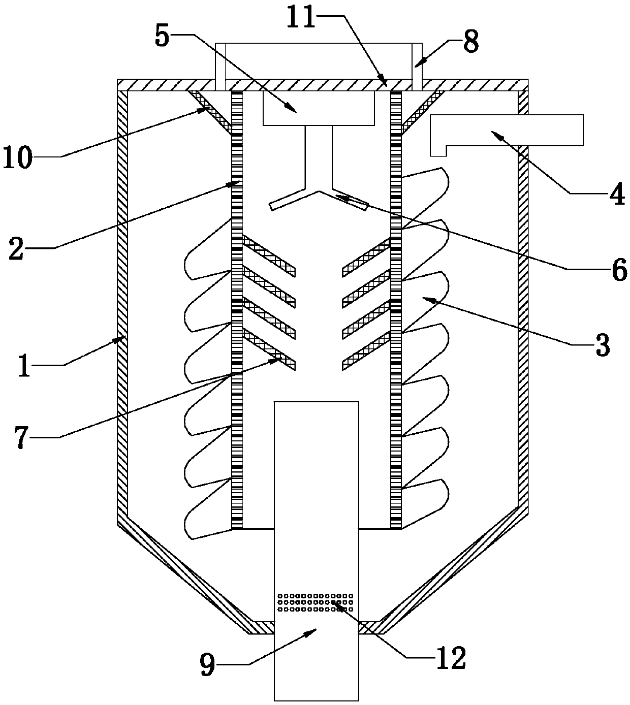
[0014] As shown in the figure, the centrifugal separation and recovery device of the present invention includes a casing 1 composed of a barrel in the upper half and a cone in the lower half. The casing 1 has a filter cartridge 2 vertically arranged from the top of the casing. The outer circumferential surface of the filter cartridge 2 is arranged with spiral guide vanes 3, and one side of the housing 1 is provided with an oil and gas inlet pipe 4 close to the outer surface of the filter cartridge 2 and above the uppermost spiral guide vane. The end of 4 is set as an elbow joint, and the elbow joint opens in the direction of the spiral guide vane 3. The top of the housing 1 is provided with an oil and gas separation umbrella 6 in the filter cylinder driven by the power unit 5, and the filter cylinder 2...


PUM


Abstract

The invention discloses a centrifugal separation and recycling device. The centrifugal separation and recycling device comprises a shell, wherein a filtering cartridge is arranged in the shell; spiraltype flow guiding blades are distributed on the surface of an outer circumference of the filtering cartridge; an oil-gas inlet pipe is arranged on one side of the shell; an oil-gas separation umbrella is arranged on the top of the shell; oil dispersion plates are arranged on the inner surface of the filtering cartridge, are uniformly distributed on the inner surface of the filtering cartridge andextend downwards aslant along the center of the filtering screen; a gas outlet is formed in the top of the shell; an oil-liquid drainage pipe is arranged at the bottom of the shell; and the top end of the oil-liquid drainage pipe is positioned below the oil dispersion plates and can enable the oil liquid accommodated on the oil dispersion plates to flow into the oil-liquid drainage pipe. By adopting the structure, through skillful structural design, operation is carried out in a swirling flow centrifugation way, so that a separation effect is greatly improved; and additionally, through arrangement of the oil dispersion plates, an efficient treatment effect of gas-liquid separation is realized again, and the oil liquid can successfully flow into the oil-liquid drainage pipe, and thus, theproblems of wastewater, secondary pollution and the like are avoided, and the treatment cost is greatly reduced.

Description

Technical field [0001] The invention relates to a separation and recovery device, in particular to a centrifugal separation and recovery device. Background technique [0002] In the process of waste gas recovery and treatment in oil product loading and transportation occasions such as oil depots, refineries, and docks, it is necessary to recover the toxic and harmful waste gas emitted into liquid oil, which can avoid the discharge of a large number of pollutants and at the same time have a greater recovery economy benefit. [0003] In the prior art, the waste gas generated in these occasions is basically untreated and directly discharged. In some cases, washing + adsorption method, low temperature plasma removal method, and oxidation incineration method are used. These treatment methods can achieve certain effects, but often there are problems in treatment. If it is in place, a large amount of waste water will be generated, secondary pollution will be formed, and the treatment cos...

Claims


Application Information

Patent Timeline
Patent Type & Authority Applications(China)
IPC IPC(8): B01D50/00
CPCB01D50/20
Inventor 徐广林王友红奚雯杰
Owner 江苏中远环保科技有限公司
Why Eureka
Try Eureka