Special-shaped hole processing method based on spatially shaped femtosecond laser layered scanning

A technology of femtosecond laser and space shaping, which is applied in the field of femtosecond laser application, to achieve the effect of avoiding uneven ablation, high special-shaped hole processing, and high degree of freedom

Inactive Publication Date: 2020-03-13
TSINGHUA UNIV +1
View PDF5 Cites 12 Cited by
  • Summary
  • Abstract
  • Description
  • Claims
  • Application Information

AI Technical Summary

Problems solved by technology

[0005] The purpose of the present invention is to solve several problems existing in the conventional femtosecond laser machining of special-shaped holes, and to propose a special-shaped hole processing system based on space-shaping femtosecond laser layered scanning. Femtosecond laser with Gaussian distribution is shaped into a flat-hat beam with uniform energy distribution after focusing

Method used


Image

  • Special-shaped hole processing method based on spatially shaped femtosecond laser layered scanning
  • Special-shaped hole processing method based on spatially shaped femtosecond laser layered scanning
  • Special-shaped hole processing method based on spatially shaped femtosecond laser layered scanning

Examples


Embodiment 1

[0034] Embodiment 1: processing special-shaped holes on the surface of a PMMA sample (polymethyl methacrylate) with a space-shaping femtosecond laser.

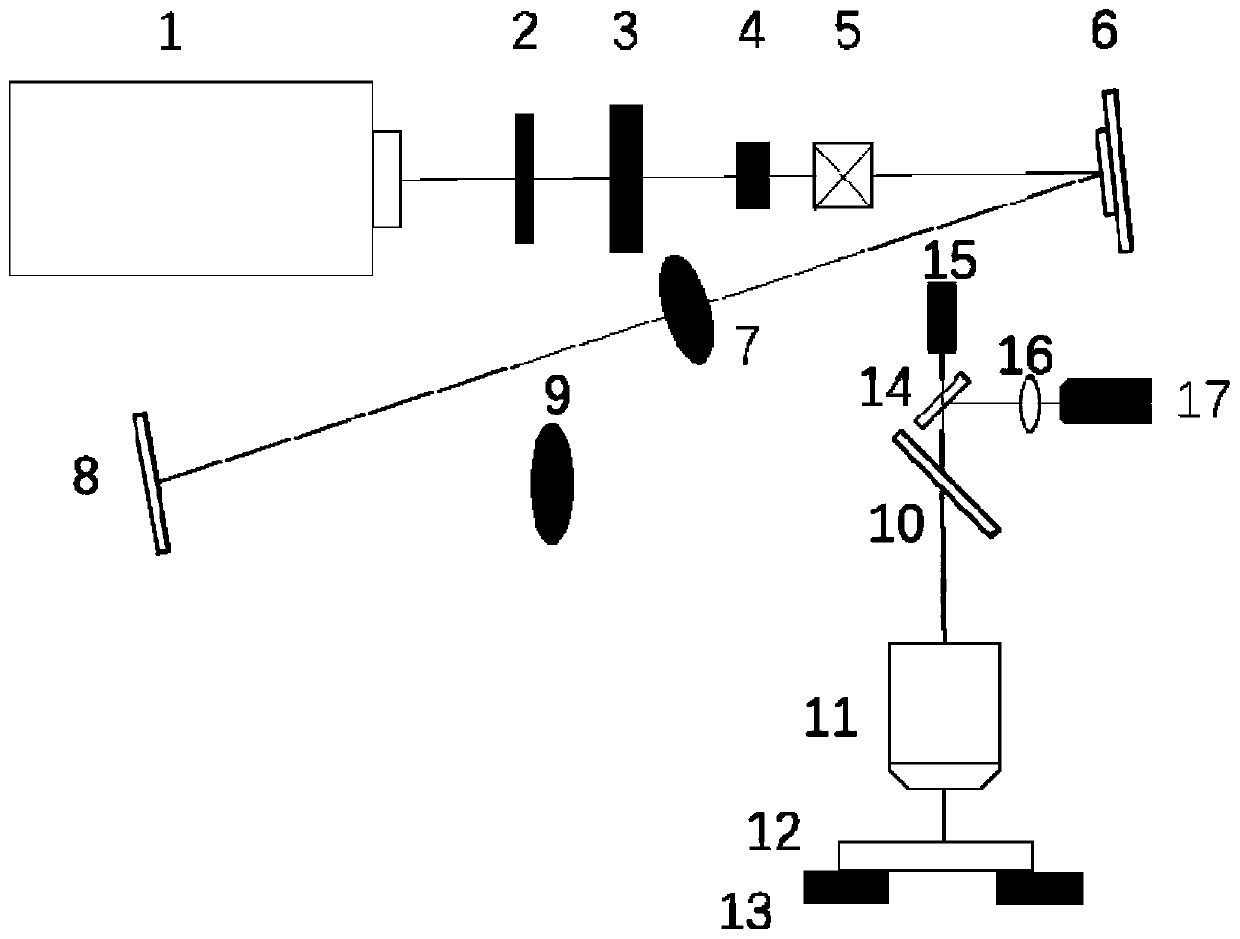
[0035] The specific processing steps of this embodiment are as follows: turn on the laser, wait for 20-30 minutes to stabilize the light output of the laser, and place each optical path element according to the figure 1Sequentially placed on the optical bench, and then the femtosecond laser is collimated and adjusted so that it can be irradiated on the surface of the PMMA sample without shaping and focusing. The femtosecond laser pulse repetition frequency of the femtosecond laser 1 is set to 1000 Hz, and the beam waist diameter before laser focusing is controlled at 5 mm. Under the operation of the control program of the six-dimensional translation stage 13, the focal plane of the processing objective lens 11 is determined at the end of the processing optical path, so that the focus of the processing objective lens 11 is exac...

Embodiment 2

[0037] Embodiment 2: Processing special-shaped holes on the surface of PDMS sample (polydimethylsiloxane) with space-shaping femtosecond laser.

[0038] The specific processing steps of this embodiment are as follows: turn on the laser, wait for 20-30 minutes to stabilize the light output of the laser, and place each optical path element according to the figure 1 Sequentially placed on the optical bench, and then the femtosecond laser is collimated and adjusted so that it can be irradiated on the surface of the PDMS sample without shaping and focusing. The femtosecond laser pulse repetition frequency of the femtosecond laser 1 is set to 1000 Hz, and the beam waist diameter before laser focusing is controlled at 7 mm. Under the operation of the control program of the six-dimensional translation stage 13, the focal plane of the processing objective lens 11 is determined at the end of the processing optical path, so that the focus of the processing objective lens 11 is exactly lo...


PUM

PropertyMeasurementUnit
wavelengthaaaaaaaaaa

Abstract

The invention relates to a special-shaped hole processing method based on spatially shaped femtosecond laser layered scanning, and belongs to the technical field of femtosecond laser applications. According to the processing system, a space shaping technology is adopted to shape traditional femtosecond laser with Gaussian distribution in a space into a flat-top light beam with uniform energy distribution after focusing, a laser scanning path and parameters are set, and high-quality complex special-shaped hole processing is realized. When the spatially shaped femtosecond laser is applied to scanning of a special-shaped hole, energy distribution of the shaped flat-top light beam is relatively average, so that non-ideal processing results caused by uneven ablation can be effectively avoided.When the spatially shaped femtosecond laser is applied to scanning of the special-shaped hole, the shape, the size, the depth and the taper of the special-shaped hole can be conveniently adjusted through the layered design of the scanning path, and special-shaped hole processing with a high freedom degree is realized.

Description

technical field [0001] The invention relates to a special-shaped hole processing system based on space-shaping femtosecond laser layered scanning, and belongs to the technical field of femtosecond laser application. Background technique [0002] Today, with ever-increasing manufacturing requirements in demanding applications, microfabrication and microfabrication have become an integral part of the industry. Micropores are the most common structure and are widely used in aviation, biology, chemical industry, new energy and other fields. The traditional means of processing microholes mainly include mechanical drilling, electric spark drilling, electrochemical drilling, electron beam drilling, focused ion beam drilling and laser beam drilling. [0003] However, in practical applications, each micro-hole processing method has certain limitations. Mechanical drilling relies on tools for cutting, so it cannot process hard materials. And because the micron-sized drill bit is li...

Claims


Application Information

Patent Timeline
Patent Type & Authority Applications(China)
IPC IPC(8): B23K26/384B23K26/06B23K26/70
CPCB23K26/0643B23K26/0648B23K26/384B23K26/70
Inventor 姜澜李佳群闫剑锋
Owner TSINGHUA UNIV
Why Eureka
Try Eureka