
METHOD OF MANUFACTURING SiC SINGLE CRYSTAL AND COVERING MEMBER

A manufacturing method and technology of coated components, applied in the direction of single crystal growth, single crystal growth, chemical instruments and methods, etc., can solve problems such as single crystal defects, and achieve the effect of suppressing flying

Inactive Publication Date: 2020-03-13
RESONAC HOLDINGS CORPORATION
View PDF5 Cites 5 Cited by
  • Summary
  • Abstract
  • Description
  • Claims
  • Application Information

AI Technical Summary

Problems solved by technology

[0008] However, there are cases where defects and the like are contained in the grown single crystal, and a method for further improving the quality of the SiC single crystal is required.

Method used


Image

  • METHOD OF MANUFACTURING SiC SINGLE CRYSTAL AND COVERING MEMBER
  • METHOD OF MANUFACTURING SiC SINGLE CRYSTAL AND COVERING MEMBER
  • METHOD OF MANUFACTURING SiC SINGLE CRYSTAL AND COVERING MEMBER

Examples


no. 1 Embodiment approach

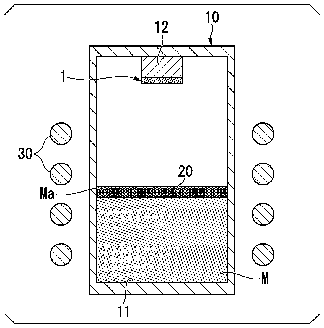
[0044] figure 1 It is a cross-sectional view of a crucible for explaining the method for producing a SiC single crystal according to the first embodiment. First, the crucible 10 used in the method of producing a SiC single crystal will be described. figure 1 The internal structure of the crucible 10 and the heating part 30 which heats the crucible 10 are shown in figure.

[0045] The crucible 10 is a container surrounding an inner space. figure 1 The shown crucible 10 has an inner bottom 11 and a crystal setting portion 12 opposite to the inner bottom 11 . The raw material M is accommodated in the inner bottom 11 . The seed crystal 1 is set in the crystal setting part 12 . For example, the crystal installation part 12 protrudes toward the raw material M in a cylindrical shape at a central position viewed from the raw material M side. For the crystal placement portion 12, for example, a carbon material such as graphite can be used. The crystal installation part 12 is not ...

Embodiment 1

[0084] "Example 1"

[0085] First, a crucible provided with a cylindrical internal space inside was prepared. Then, the inner bottom of the crucible was filled with SiC powder raw material in a powder state as a raw material. The particle size of the powder particles was set to 300 μm.

[0086] Next, a porous body composed of a SiC sintered body was provided on the raw material powder. The entire surface of the raw material is covered with the porous body. The average pore diameter of the porous body was 150 μm. The average pore diameter of the porous body was measured using an optical microscope to measure the average pore diameter of pores within a predetermined range. This value is not significantly different from that measured using a mercury porosimeter. In addition, the porosity of the porous body was 45%. The thickness of the porous body was set to be 15% of the height of a vertical line hanging from the surface of the raw material to the inner bottom.

[0087] T...

Embodiment 2

[0091] "Example 2"

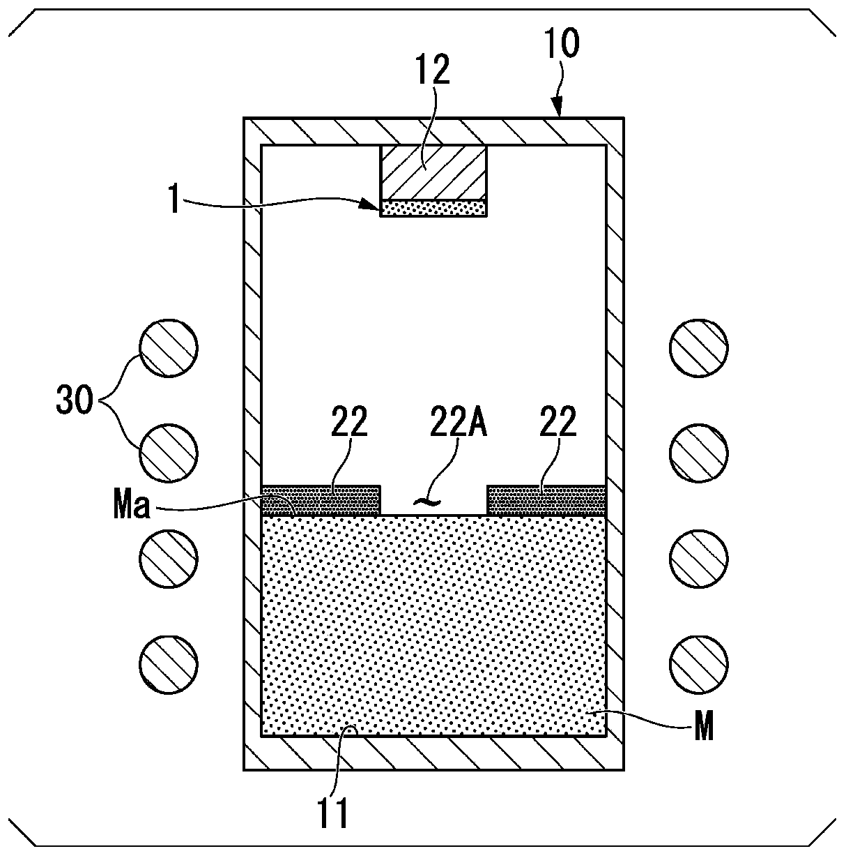
[0092] In Example 2, using image 3 In the porous body 22 of Modification 2 shown, the coverage rate of the raw material surface of the porous body is changed. Other conditions are identical with embodiment 1. The material coverage ratio of the porous body was 0% (corresponding to Comparative Example 1), 10%, 20%, 30%, 40%, 50%, 60%, 70%, 80%, 90%, 100% (corresponding to Example 1).

[0093] Figure 4 The examination results of Example 2 are shown. Figure 4 The abscissa of is the coverage rate of the raw material surface of the porous body. Figure 4 The vertical axis of is the ratio of the carbon inclusion density of each coverage ratio when the carbon inclusion density when the coverage ratio is 0% (corresponding to Comparative Example 1) is 100%.

[0094] Such as Figure 4 As shown, if the surface of the raw material is covered with a porous body, the density of the carbon-included body decreases. In addition, if the coverage exceeds 70%, the r...


PUM

PropertyMeasurementUnit
porosityaaaaaaaaaa
porosityaaaaaaaaaa
particle diameteraaaaaaaaaa

Abstract

The present invention provides a method of manufacturing a SiC single crystal and a covering member. The method of manufacturing a SiC single crystal includes: a storing step of storing a SiC source,which is a powder, in an inner bottom part of a crucible, wherein the crucible is configured to store the SiC source and to attach a seed crystal to a position of the crucible which faces the SiC source; a placing step of placing a porous material on at least a portion of a first surface of the SiC source, wherein the first surface is positioned on a side of the seed crystal; and a crystal growthstep of sublimating the SiC source by heating to grow a crystal on the seed crystal, in which the porous material is formed of carbon or a carbide, and the hole diameter of the porous material is smaller than the average particle diameter of the SiC source.

Description

technical field [0001] The present invention relates to a method for producing a SiC single crystal and a coated member. [0002] This application claims priority based on Patent Application No. 2018-167065 filed in Japan on September 6, 2018, the contents of which are incorporated herein by reference. Background technique [0003] The insulation breakdown electric field of silicon carbide (SiC) is an order of magnitude larger than that of silicon (Si), and the band gap is 3 times larger than that of silicon (Si). In addition, silicon carbide (SiC) has characteristics such as thermal conductivity about three times higher than that of silicon (Si). It is expected that silicon carbide (SiC) will be applied to power devices, high-frequency devices, and high-temperature operating devices. [0004] Devices such as semiconductors use SiC epitaxial wafers in which epitaxial films are formed on SiC wafers. The epitaxial film formed on the SiC wafer by chemical vapor deposition (C...

Claims


Application Information

Patent Timeline
Patent Type & Authority Applications(China)
IPC IPC(8): C30B23/02C30B29/36
CPCC30B23/02C30B29/36C30B23/00C30B23/005
Inventor 保坂祥辉
Owner RESONAC HOLDINGS CORPORATION
Learn More