Vein vessel recognition system based on vein puncture robot

A venous blood vessel and identification system technology, applied in the directions of blood vessel pattern, biometric recognition, character and pattern recognition, etc., can solve problems such as difficulty in venipuncture experience and proficiency, improve safety and detectability, and improve success rate , the effect of reducing the risk of puncture

Inactive Publication Date: 2020-03-17
HARBIN INST OF TECH
View PDF4 Cites 9 Cited by
  • Summary
  • Abstract
  • Description
  • Claims
  • Application Information

AI Technical Summary

Problems solved by technology

[0003] The purpose of the present invention is to solve the problem that the existing venipuncture relies heavily on the experience and proficiency of medical...

Method used


Image

  • Vein vessel recognition system based on vein puncture robot

Examples


specific Embodiment approach 1

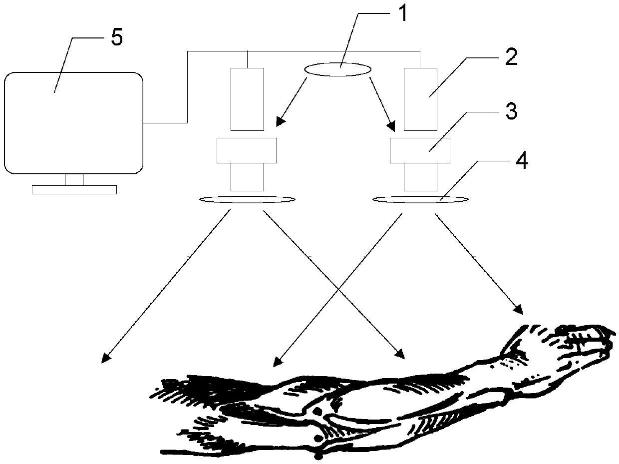
[0011] Specific implementation mode one: combine figure 1 Describe this embodiment, a vein recognition system based on a venipuncture robot described in this embodiment, is characterized in that the vein recognition system includes a near-infrared light source module 1, two near-infrared image acquisition modules and an image processing module 5;

[0012] The near-infrared light source module 1 is used to provide near-infrared light;

[0013] Two near-infrared image acquisition modules are used to collect near-infrared images of venous blood vessels respectively, and send the acquired two near-infrared images to the image processing module 5 respectively;

[0014] The image processing module 5 is used to perform image processing on the two near-infrared images respectively, obtain a complete point cloud image of the upper surface of the venous vessel, and display the point cloud image of the upper surface of the venous vessel in real time.

[0015] In this embodiment, the im...

specific Embodiment approach 2

[0016] Specific embodiment 2: This embodiment is to further limit the venipuncture robot-based venous vessel recognition system described in specific embodiment 1. In this embodiment, the near-infrared image acquisition module includes an infrared enhanced camera 2, Lens 3 and near-infrared light narrow-band filter 4;

[0017] The lens 3 is arranged on the outer end of the infrared enhanced camera 2, and the near-infrared narrow-band filter 4 is arranged on the lens 3; the near-infrared narrow-band filter 4 is used to eliminate the interference of external ambient light, so as to facilitate the acquisition of clear near-infrared blood vessels. Infrared image;

[0018] The image signal output end of the infrared enhanced camera 2 is connected with the image signal input end of the image processing module 5 .

[0019] In this embodiment, the images captured by the infrared enhanced camera 2 are transmitted to the image processing module 5 through USB.

[0020] In this embodime...

specific Embodiment approach 3

[0021] Specific Embodiment 3: This embodiment is to further limit the venipuncture robot-based venous blood vessel identification system described in Specific Embodiment 1. In this embodiment, the near-infrared light source module 1 is: multiple wavelengths of The 850nm LED light source is combined with the light source composed of a diffuser plate.


PUM


Abstract

The invention discloses a vein vessel recognition system based on a venipuncture robot, which belongs to the technical field of electromechanical integration, and aims at solving the problems that existing venipuncture greatly depends on experience and proficiency of medical staff, and the medical staff is very difficult to accurately conduct venipuncture on special patients. A near-infrared lightsource module is used for providing near-infrared light; wherein the two near-infrared image acquisition modules are used for acquiring near-infrared images of veins respectively and sending the acquired two near-infrared images to the image processing module respectively; and the image processing module is used for performing image processing on the two near-infrared images to obtain a completevein blood vessel upper surface point cloud picture, and displaying the vein blood vessel upper surface point cloud picture in real time. The system has the beneficial effect of improving the venipuncture success rate.

Description

technical field [0001] The invention belongs to the technical field of mechanical and electrical integration. Background technique [0002] Piercing a vein to obtain a blood sample or injecting a drug is one of the most common medical procedures, whether in a large hospital or a small clinic. At present, clinical venipuncture mainly relies on skilled medical personnel, who need special training and a lot of attempts. The commonly used venous puncture method is as follows: tie a tourniquet on the patient, and then let him make a fist to make the venous blood vessel stand out so as to facilitate venipuncture. The success rate of this puncture procedure greatly depends on the experience and proficiency of the medical staff. For patients with dark skin, deep veins, covering injuries, tattoos and hair, especially infants, the elderly, obese and dehydrated patients etc., because it is difficult to locate the venous vessel position accurately, it is very difficult to want to carr...

Claims


Application Information

Patent Timeline
IPC IPC(8): A61B5/00G06K9/00G06T5/00G06T5/40G06T7/136G06T7/80G06T15/08
CPCA61B5/0064A61B5/7203G06T15/08G06T7/80G06T5/002G06T5/40G06T7/136G06T2207/10028G06T2207/10048G06T2207/30101G06V40/10G06V40/14
Inventor 姜力何天宝郭闯强任浩董杰
Owner HARBIN INST OF TECH
Why Eureka
Try Eureka