Boiler flue gas white smoke removal system

A boiler flue gas and flue gas technology, applied in gas treatment, dispersed particle separation, membrane technology, etc., can solve the problem of uneven heating of flue gas, achieve uniform and stable heat distribution, uniform heating, and prevent local white smoke.

Pending Publication Date: 2020-03-17
ANHUI UNIVERSITY OF TECHNOLOGY
View PDF0 Cites 12 Cited by
  • Summary
  • Abstract
  • Description
  • Claims
  • Application Information

AI Technical Summary

Problems solved by technology

[0008] The purpose of the present invention is to overcome the deficiency caused by uneven heating of the flue gas caused by improper control of the partial pressure of the vortex tube air flow in the existing whitening system, and to provide a boiler flue gas whitening system, through the cooperation of the split chamber and the mixing chamber The hot air flow can be shunted and depressurized, which can prevent the backflow of the flue gas and achieve uniform heating of the flue gas, improving the whitening effect

Method used


Image

  • Boiler flue gas white smoke removal system
  • Boiler flue gas white smoke removal system
  • Boiler flue gas white smoke removal system

Examples


Embodiment 1

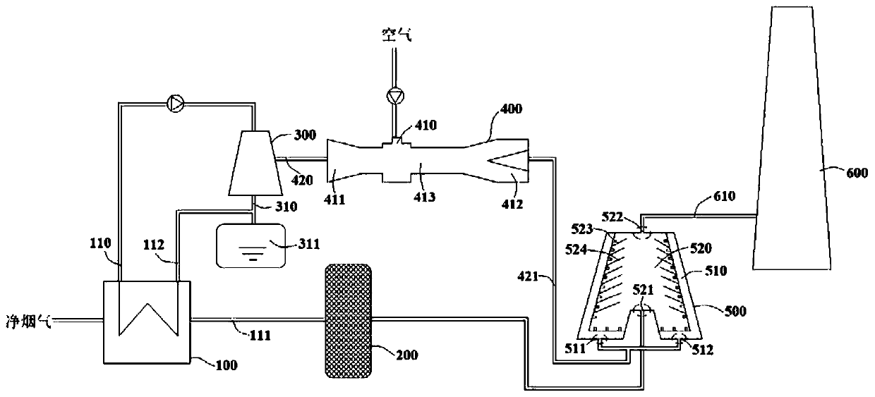
[0042] combine figure 1 and figure 2 , a boiler flue gas dewhitening system in this embodiment includes a flue gas condenser 100, a cooling tower 300, a vortex tube 400, and a flue gas heater 500 connected in sequence, and the vortex tube 400 is used to separate hot and cold air streams, which generate The cold air flow is used in the cooling tower 300 to cool down the circulating water. The flue gas heater 500 has a double-layer structure, which includes an outer splitting chamber 510 and an inner mixing chamber 520. The flue gas condensed by the flue gas condenser 100 It passes into the mixing chamber 520, and the mixing chamber 520 communicates with the flow diversion chamber 510 through the flow guide tube 523 arranged on its surface. The hot gas flow generated by the vortex tube 400 flows into the flow distribution chamber 510 and enters the mixing chamber 520 along the flow guide tube 523 to realize the integration with the flue gas. mixed heat transfer.

[0043] In t...

Embodiment 2

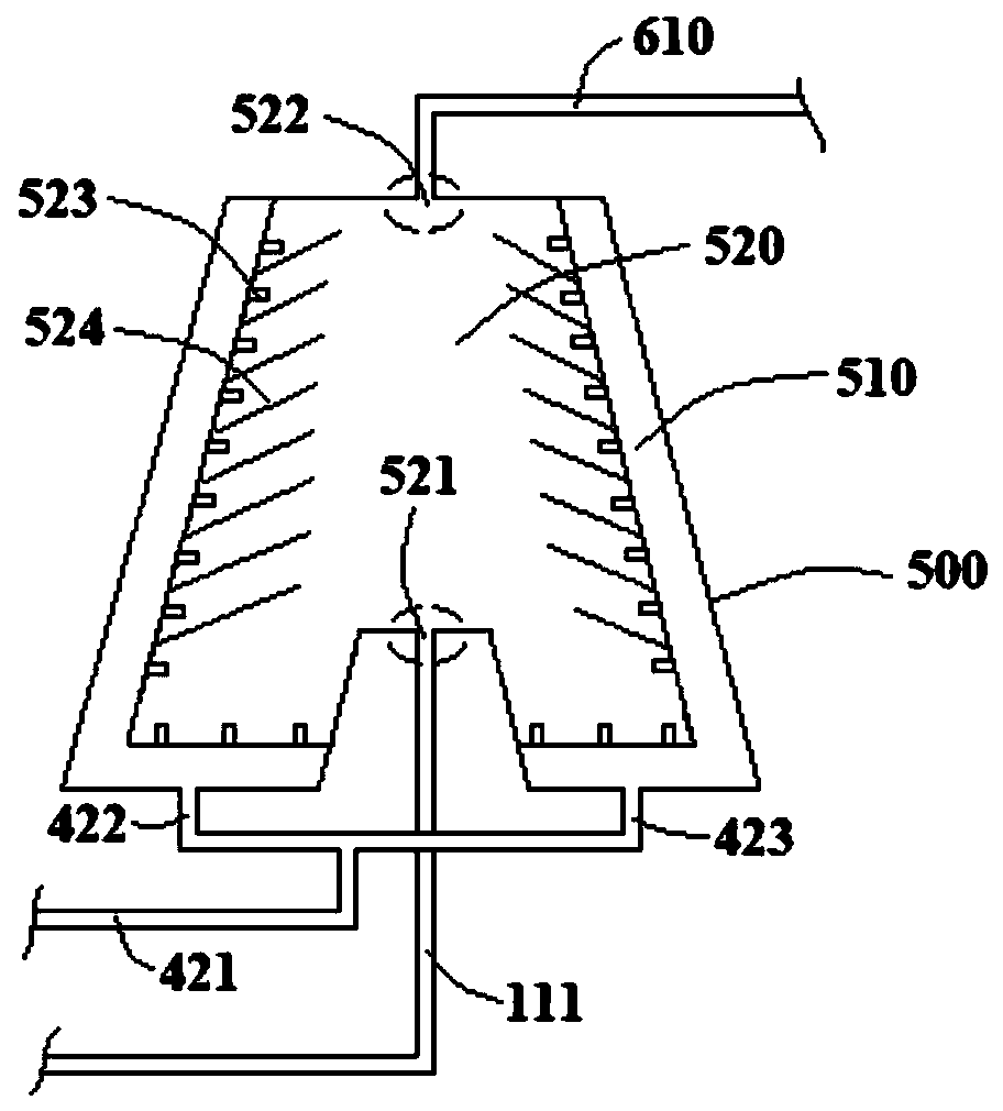
[0048] A boiler flue gas de-whitening system in this embodiment, its structure is basically the same as that in Embodiment 1. Further, the bottom wall of the diversion chamber 510 includes end horizontal sections 530 at both ends and a central middle protruding section 531, the middle protruding The section 531 is provided with a flue gas inlet 521 communicating with the mixing chamber 520 , and the end horizontal section 530 is provided with an air inlet communicating with the splitting chamber 510 . Preferably, the ratio of the height of the middle extension section 531 to the height of the flue gas heater 500 in this embodiment is 1 / 6˜1 / 4.

[0049] In order to promote the uniform mixing of flue gas and hot air flow, in this embodiment, the bottom wall of the distribution chamber 510 is arranged in a three-section structure, wherein the middle middle extension section 531 is protruded, and the flue gas inlet 521 is arranged on the middle extension section 531, so as to send ...

Embodiment 3

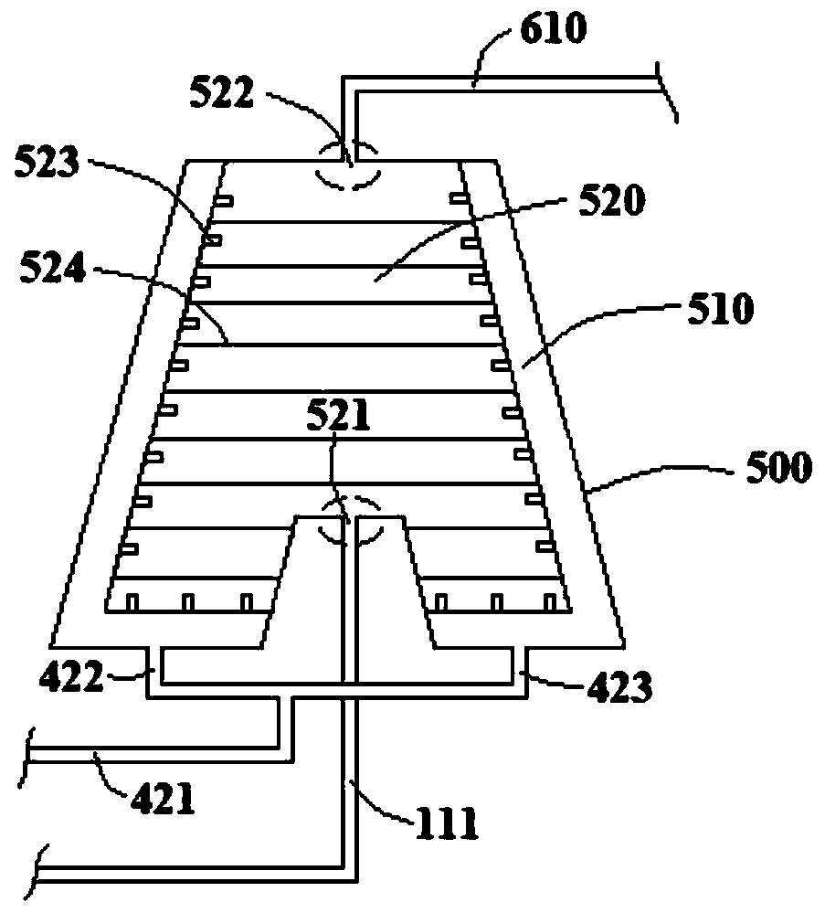
[0053] combine image 3 , a boiler flue gas dewhitening system in this embodiment, its structure is basically the same as in Embodiment 2, further, a flue gas baffle 524 is horizontally arranged on the side wall of the mixing chamber 520 in this embodiment, and the flue gas baffle 524 is provided with guide holes 525, and the flue gas baffles 524 and guide pipes 523 are arranged alternately. The flue gas baffle 524 in this embodiment communicates with the inner side wall of the mixing chamber 520, and a guide hole 525 is opened on the flue gas baffle 524, which can disperse the flue gas and further promote the mixing and uniform heating of the flue gas by the hot air flow .


PUM


Abstract

Belonging to the technical field of environmental protection, the invention discloses a boiler flue gas white smoke removal system. According to the boiler flue gas white smoke removal system, a cooling tower and a vortex tube are arranged between a flue gas condenser and a flue gas heater, and the flue gas condenser and the vortex tube are separated by the cooling tower, thus preventing reductionof flue gas condensation efficiency and heat exchange efficiency caused by mixing of cold air flow and hot air flow. A flow splitting chamber on the outer layer of the flue gas heater is arranged along the circumferential direction of an mixing chamber on the inner layer, the mixing chamber is communicated with the flow splitting chamber through flow guide pipes arranged on the surface of the mixing chamber, under the flow splitting effect of the flow guide pipes, the hot air flow generates uniform and stable thermal shunts, thus achieving uniform heating of flue gas in the mixing chamber; and the thermal shunts cannot press flue gas into a flue gas inlet pipeline due to too large air pressure, thus effectively preventing backflow of flue gas and improving the white smoke removal effect.

Description

technical field [0001] The invention belongs to the technical field of environmental protection, and more specifically relates to a boiler flue gas dewhitening system. Background technique [0002] At present, the desulfurization system of more than 90% of coal-fired power plants in my country adopts the limestone-gypsum wet desulfurization method. Most of this desulfurization process uses spray washing to remove sulfur dioxide. The boiler flue gas enters the desulfurization tower after being treated by denitrification and dust removal processes. The temperature of the wet desulfurization reaction is controlled at 45-55°C. The gas is wet saturated flue gas, and the dew point temperature of flue gas and water is close at this time. If the flue gas is directly discharged into the ambient air with low temperature and humidity in a saturated state, "white smoke" will be produced, which contains a large amount of water vapor and some pollutants. According to the mechanism of wh...

Claims


Application Information

Patent Timeline
Patent Type & Authority Applications(China)
IPC IPC(8): B01D53/26
CPCB01D53/005B01D53/26B01D53/265B01D2258/0283
Inventor 楚化强颜岩闫仕成王浩余波
Owner ANHUI UNIVERSITY OF TECHNOLOGY
Why Eureka
Try Eureka