Continuous working photovoltaic cleaning robot

A cleaning robot and photovoltaic technology, applied in the cleaning method using tools, photovoltaic modules, photovoltaic power generation, etc., can solve the problems of increasing the difficulty of continuous operation of cleaning machines, low cleaning efficiency, high cost, etc., to improve flexibility and environmental protection The effect of adaptability, improving work efficiency and improving cleaning efficiency

Pending Publication Date: 2020-03-17
SHENZHEN KWUNPHI ROBOT CO LTD
View PDF0 Cites 5 Cited by
  • Summary
  • Abstract
  • Description
  • Claims
  • Application Information

AI Technical Summary

Problems solved by technology

[0003] When the photovoltaic array is built, due to factors such as terrain, there will be some unevenness and small intervals between the photovoltaic panels, resulting in sometimes some 1mm to 7mm steps perpendicular to the panels and 0mm to 0mm. With a gap of 30mm, the small movable automatic cleaning equipment in the industry cannot realize automatic spanning at present
And there is a certain inclination during construction, which increases the difficulty of the continuous operation of the cleaning machine on the photovoltaic panel. At present, the small mobile automatic cleaning equipment in the industry can only realize the operation with a small slope
[0004] However, there is a distance of about 0.5 meters to 30 meters between photovoltaic arrays. At present, the small automatic cleaning equipment in the industry usually cannot span, or the track is laid on the ground to be transported by a pick-up equipment.
The method of laying tracks on the ground is greatly limited by the constraints of terrain and environment, and the cost is high. After cleaning a photovoltaic array, it needs to return to the pick-up equipment in the same way, and the cleaning efficiency is low.

Method used


Image

  • Continuous working photovoltaic cleaning robot
  • Continuous working photovoltaic cleaning robot
  • Continuous working photovoltaic cleaning robot

Examples


Embodiment Construction

[0044] The present invention will be further described below with reference to the accompanying drawings and specific embodiments.

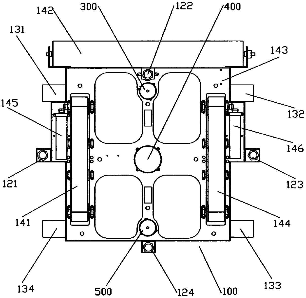
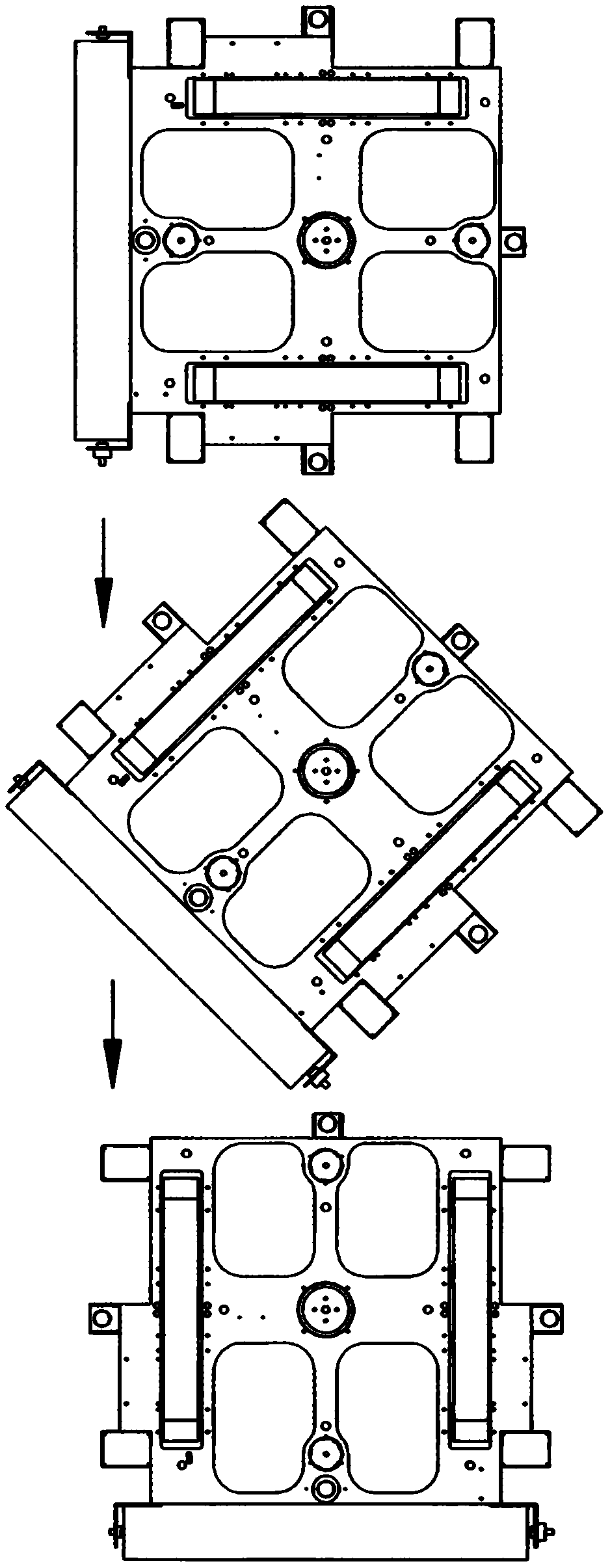
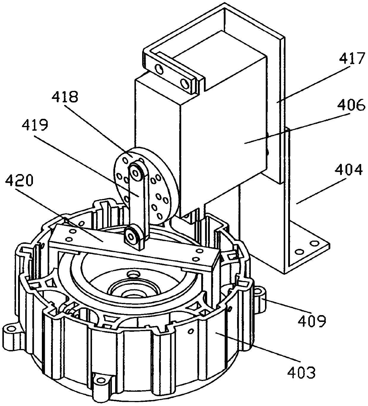
[0045] Such as Figure 1 to Figure 23 As shown: it is a photovoltaic cleaning robot with continuous operation provided by the embodiment of the present invention. The photovoltaic cleaning robot includes a fuselage 100. The fuselage 100 is provided with a driving mechanism, a walking device and a cleaning mechanism 142. The walking device drives the fuselage 100 to clean Walking, the cleaning mechanism 142 is fixedly arranged on the outer wall of the front end of the fuselage 100, and the cleaning mechanism 142 performs cleaning operations under the drive of the driving mechanism. The walking device includes a crawler walking device and a mechanical leg walking device. plate 150, the support plate 150 is provided with installation holes 151, and the four corners of the support plate 150 located in the installation holes 151 are respectively provi...


PUM


Abstract

The invention relates to a continuous working photovoltaic cleaning robot. The photovoltaic cleaning robot comprises a robot body. A driving mechanism, a walking mechanism and a sweeping mechanism arearranged on the robot body. The walking device drives the robot body to walk. The sweeping mechanism conducts sweeping work under the drive of the driving mechanism. The walking device comprises a crawler travel unit and mechanical leg walking devices. A supporting plate is fixedly arranged above the robot body, an installation hole is formed in the supporting plate, and the mechanical leg walking devices are arranged at the positions, located at the four corners of the installation hole, of the supporting plate. An adsorption assembly is arranged at the bottom of the robot body, and the robot body is adsorbed on the work plane through the adsorption mechanism. By means of the arrangement of the walking device and due to the fact that every two adjacent photovoltaic plate arrays are connected through a deck, continuous work can be conducted on the photovoltaic plate arrays, continuous work can also be conducted between the photovoltaic plate arrays, and therefore the adaptability andthe cleaning efficiency of the photovoltaic cleaning robot are improved.

Description

technical field [0001] Embodiments of the present invention relate to the technical field of photovoltaic cleaning robots, in particular to a photovoltaic cleaning robot that operates continuously. Background technique [0002] The sustainable development and environmental protection of solar power make it one of the most ideal renewable energy technologies, among which photovoltaic power generation is the main one, and photovoltaic ash deposition effect is one of the biggest problems encountered in the large-scale application of photovoltaic power generation First, large-scale photovoltaic power plants are mostly built in areas with long sunshine hours and little rain. If they are not cleaned for a long time, the power generation will drop by 20%-30%, causing a lot of economic losses. Therefore, how to economically and reasonably solve the problem of dust accumulation has become a key task for the development of the photovoltaic industry. [0003] When the photovoltaic arr...

Claims


Application Information

Patent Timeline
Patent Type & Authority Applications(China)
IPC IPC(8): B08B1/04B08B13/00H02S40/10B25J11/00B62D57/032B62D57/024
CPCB08B1/04B08B13/00B25J11/0085B62D57/024B62D57/032H02S40/10Y02E10/50
Inventor 田殷钦陈应洪
Owner SHENZHEN KWUNPHI ROBOT CO LTD
Why Eureka
Try Eureka