Eureka AIR delivers breakthrough ideas for toughest innovation challenges, trusted by R&D personnel around the world.

Automatic copper bar transplanting warehouse

A warehouse and automatic technology, applied in the field of intelligent warehouse, can solve the problems of large storage area and space, chaotic warehouse management, unfavorable humanized management, etc., to achieve high warehouse accuracy, improved warehouse rhythm, and easy adjustment. quick effect

Pending Publication Date: 2020-03-17
杭州研卓智能科技有限公司
View PDF0 Cites 6 Cited by
  • Summary
  • Abstract
  • Description
  • Claims
  • Application Information

AI Technical Summary

Problems solved by technology

[0002] At present, the warehouse of copper bars and plates in the power industry relies on manual and forklift loading and unloading, quantity statistics, classification, palletizing, outbound management, inventory quantity statistics, management of storage specifications and existing inventory space, etc. , all rely on manual management, which greatly wastes manpower and time in the handling of in and out of the warehouse. The management of time in and out of the warehouse is relatively chaotic. It provides a relatively clear solution, which greatly solves the difficulty of warehouse space management and is effective. The efficiency of production is guaranteed and the production cost is reduced; the current operation space for copper bar plates needs to be moved in and out of the warehouse, which accounts for a large proportion of storage area and space, and wastes a lot of space. There are management defects, which are not conducive to reasonable overall management, difficult in and out of storage, difficult to retrieve data, low efficiency, and not conducive to humanized management

Method used


Image

  • Automatic copper bar transplanting warehouse
  • Automatic copper bar transplanting warehouse
  • Automatic copper bar transplanting warehouse

Examples


Embodiment Construction

[0027] Embodiments of the present invention are described below through specific examples, and those skilled in the art can easily understand other advantages and effects of the present invention from the content disclosed in this specification.

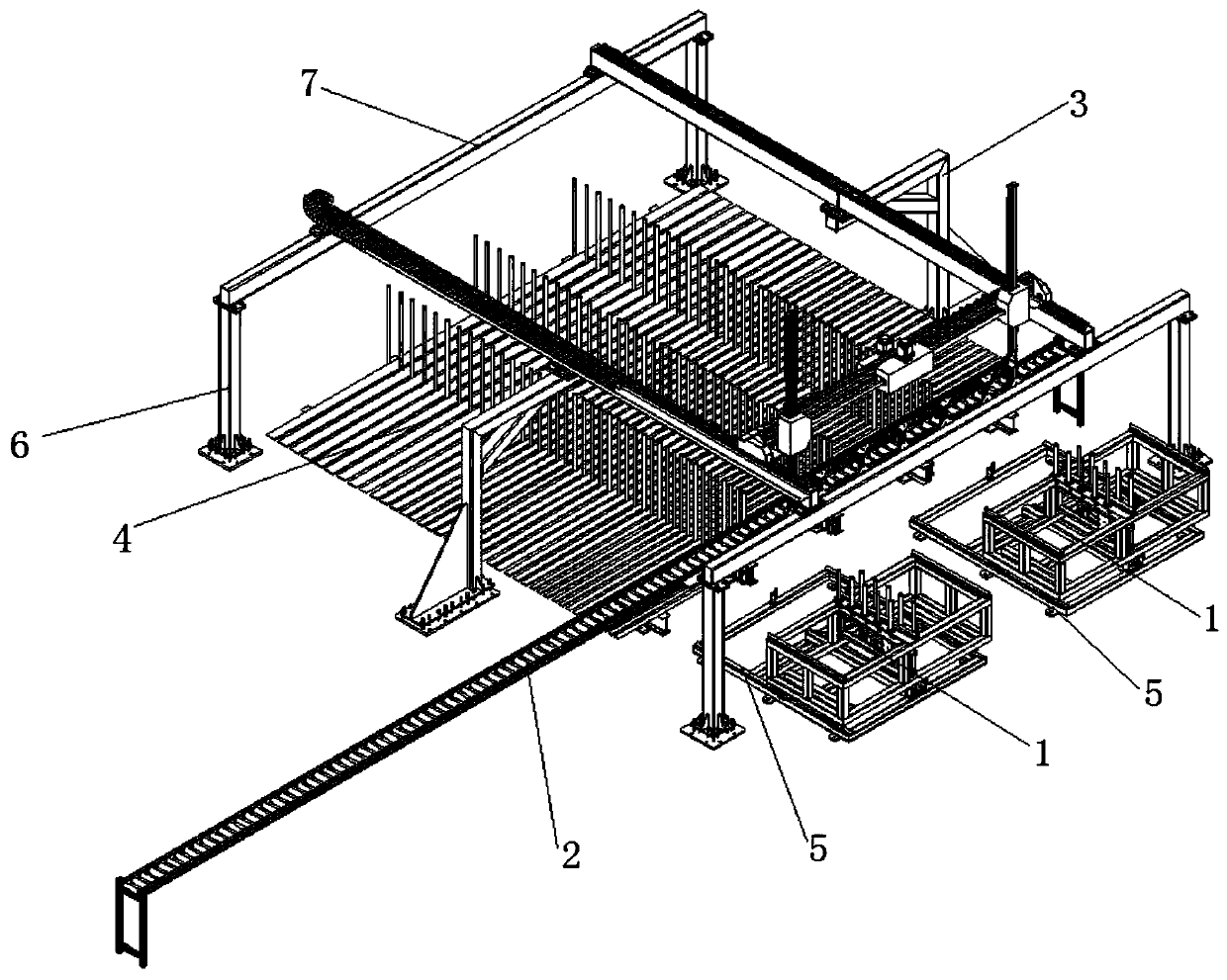
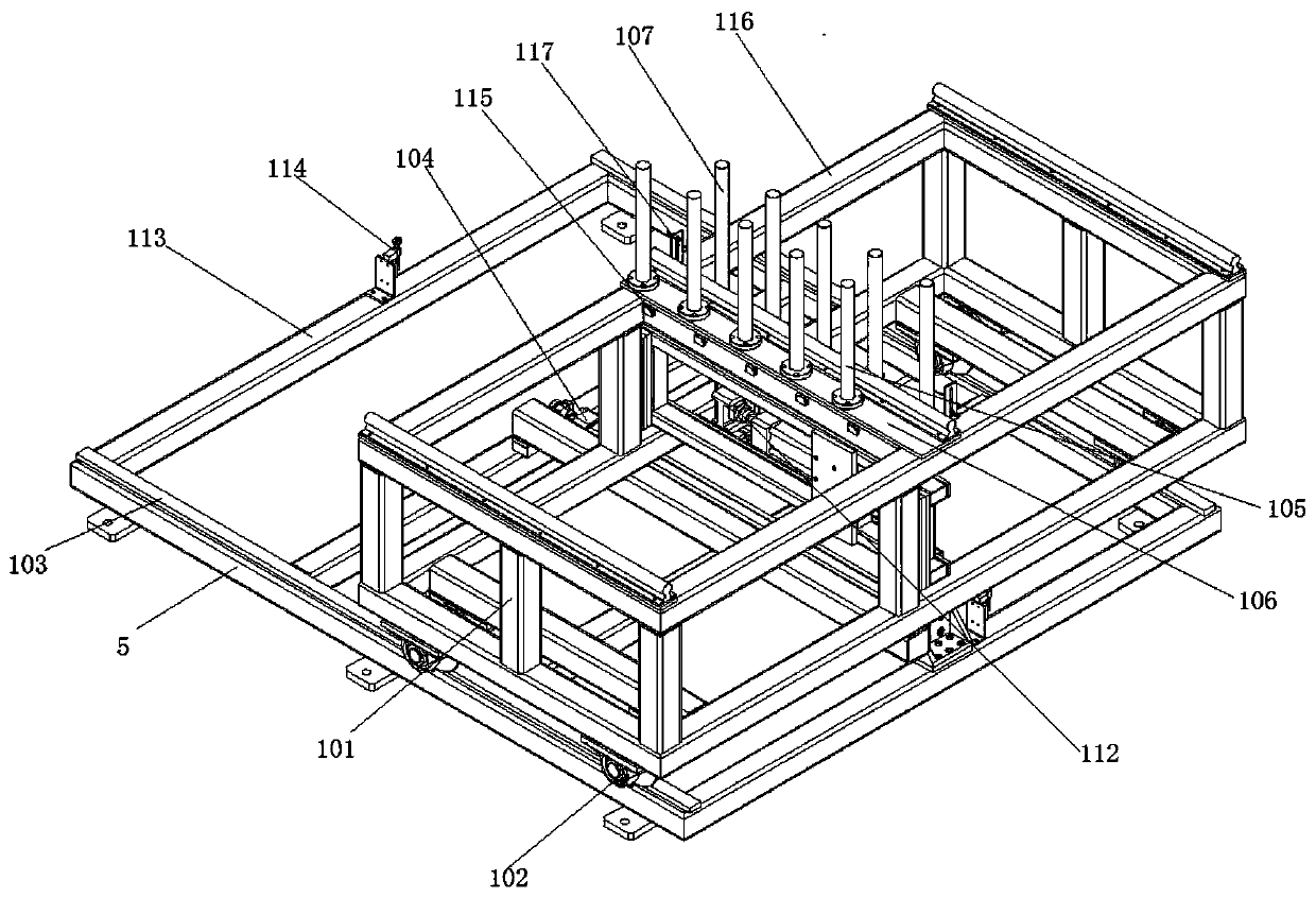
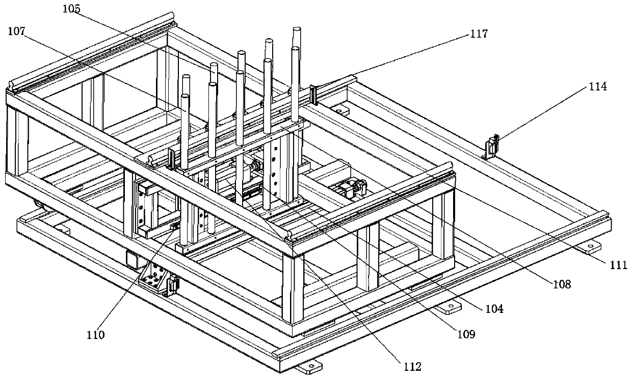
[0028] Such as figure 1 As shown in the figure, an automatic copper bar transplanting warehouse is used to carry out storage and outbound processing of copper bar workpieces. The transplanting warehouse includes a feeding and pushing platform 1, a roller conveyor line 2, a truss manipulator 3 and a copper bar Storage location 4, the loading and pushing platform 1 is located at the feeding end of the truss manipulator 3, the bottom frame 5 of the feeding and pushing platform 1 is connected to the ground by expansion bolts and fixed on the ground, and the roller conveyor line 2 is located at the truss manipulator The feeding end of 3 is used for positioning the copper bar workpiece. The truss manipulator 3 includes a steel structure ho...


PUM


Abstract

The invention relates to an automatic copper bar transplanting warehouse which is used for carrying out warehouse-in and warehouse-out treatment on copper bar workpieces. The transplanting warehouse comprises a feeding and pushing platform, a roller conveying line, a truss manipulator and a copper bar storage location. The feeding and pushing platform is located at a feeding end of the truss manipulator. A bottom rack of the feeding and pushing platform is connected and fixed to the ground through an expansion bolt. The roller conveying line is located at the feeding end of the truss manipulator so as to carry out positioning operation on the copper bar workpieces. The truss manipulator comprises a steel structure transverse shaft supported by a stand column, a grabbing mechanism and a moving mechanism, wherein the grabbing mechanism and the moving mechanism are located on the transverse shaft. And the truss manipulator is used for completing warehouse-in and warehouse-out operation ofthe workpieces, and the copper bar storage location is located right below the truss manipulator and is used for storing the copper bar workpieces. The automatic transplanting warehouse can grab thecopper bars with different specifications, is excellent in compatibility, and can carry out classified warehouse-in and warehouse-out operation according to products with different specifications.

Description

technical field [0001] The invention relates to the field of intelligent warehouses, in particular to an automatic transplanting warehouse for semi-finished copper bar plates in the electric power industry. Background technique [0002] At present, the warehouse of copper bars and plates in the power industry relies on manual and forklift loading and unloading, quantity statistics, classification, palletizing, outbound management, inventory quantity statistics, management of storage specifications and existing inventory space, etc. , all rely on manual management, which greatly wastes manpower and time in the handling of in and out of the warehouse. The management of time in and out of the warehouse is relatively chaotic. It provides a relatively clear solution, which greatly solves the difficulty of warehouse space management and is effective. The efficiency of production is guaranteed and the production cost is reduced; the current operation space for copper bar plates nee...

Claims


Application Information

Patent Timeline
Patent Type & Authority Applications(China)
IPC IPC(8): B65G1/04
CPCB65G1/04
Inventor 赵刚
Owner 杭州研卓智能科技有限公司
Why Eureka
Eureka Blog
Learn More