Supercharge Your Innovation With Domain-Expert AI Agents!

Photothermal embedded thermal power peak shaving system and method

An embedded, photothermal technology, applied in solar thermal power generation, steam engine installations, mechanical power generated by solar energy, etc., can solve problems such as high investment costs, low energy utilization rate, and weak peak-shaving ability of thermal power, so as to improve flexibility performance, enhanced deep peak-shaving capability, and the effect of saving equipment investment and operating costs

Pending Publication Date: 2020-03-17
SHANGHAI MINGHUA ELECTRIC POWER TECH & ENG +1
View PDF2 Cites 1 Cited by
  • Summary
  • Abstract
  • Description
  • Claims
  • Application Information

AI Technical Summary

Problems solved by technology

[0005] In order to solve the above technical problems, the present invention provides a photothermal embedded thermal power peak shaving system and method, which can effectively solve the problems of weak peak shaving ability of existing thermal power, unstable light energy, high investment cost, low energy utilization rate, etc. question

Method used


Image

  • Photothermal embedded thermal power peak shaving system and method

Examples


Embodiment 1

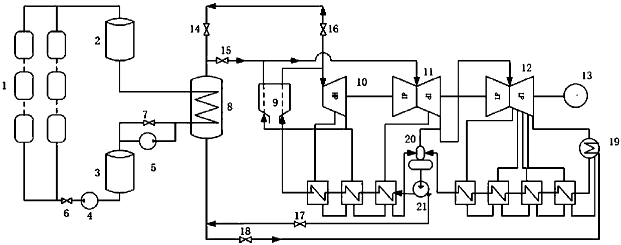
[0041] The heat collector 1 is a sunlight-focusing heat-collecting device, which can be tower-type, trough-type or disc-type heat collector, equipped with a bypass pipeline, a sun tracking system and a control system, and the inlet and outlet are respectively connected to the thermal medium storage station 2 , The cold working medium storage station 3 is connected.

[0042] Photothermal working medium is molten salt, ionic liquid (kCl, kOH, etc.), supercritical CO2 whose boiling point is higher than the boiler reheat steam temperature.

[0043]There are two parallel pipelines between the refrigerant storage station 3 and the heat exchanger 8, one of which is the passage of the refrigerant from the heat exchanger to the refrigerant storage station, and a regulating valve 7 is set, and the other is the flow of the refrigerant from the refrigerant Set the reverse pump 5 from the mass storage station to the heat exchanger channel.

[0044] The shells of the hot working medium sto...

Embodiment 2

[0051] The heat collector 1 is a sunlight-focusing heat-collecting device, which can be tower-type, trough-type or disc-type heat collector, equipped with a bypass pipeline, a sun tracking system and a control system, and the inlet and outlet are respectively connected to the thermal medium storage station 2 , The cold working medium storage station 3 is connected.

[0052] The photothermal working medium is supercritical CO2, the temperature is higher than 31.26°C, and the pressure is higher than 7.29MPa.

[0053] The solar thermal side is equipped with a CO2 injection device, and the supplementary CO2 can be extracted from the purified flue gas of the boiler.

[0054] There are two parallel pipelines between the refrigerant storage station 3 and the heat exchanger 8, one of which is the passage of the refrigerant from the heat exchanger to the refrigerant storage station, and a regulating valve 7 is set, and the other is the flow of the refrigerant from the refrigerant Set ...


PUM


Abstract

The invention provides a photothermal embedded thermal power peak shaving system and method. The system comprises a heat collector capable of collecting heat by using a photothermal working medium, aheat exchanger connected with a thermoelectric unit, a heat working medium storing station with one end connected with one end of the heat collector and with the other end connected with one end of the heat exchanger, and a cold working medium storing station with one end connected with the other end of the heat collector through a forward pump and with the other end connected with the other end of the heat exchanger through a backward pump. The photothermal embedded thermal power peak shaving system is applied to a photothermal and thermal power generation heating system, the luminous energyis converted into electric energy or thermal energy by using a thermoelectric unit thermal system, meanwhile, a part of the thermal energy of the thermoelectric unit is absorbed by using the working medium storage function of the photothermal system, the deep peak shaving capacity of the thermoelectric unit is improved, and the flexibility of the thermoelectric unit is improved.

Description

technical field [0001] The invention relates to a thermal power generation system, in particular to a peak regulation control system and method for the thermal power generation system. Background technique [0002] The power industry is the foundation of the national economy. With the change of power consumption demand and power consumption structure of power users in my country, the peak-to-valley difference between day and night gradually increases, and the peak-to-valley difference can reach 30%-40% of the peak load of power generation. under great pressure. The installed capacity of thermal power units accounts for more than 70%. When the thermal power units are in deep peak regulation, it is very easy to cause problems such as difficulty in stable combustion of the boiler and excessive environmental protection indicators. Moreover, the operating economy of thermal power units under low loads is poor, resulting in increased coal consumption. Costs go up. Utilizing heat...

Claims


Application Information

Patent Timeline
IPC IPC(8): F01K23/02F01K13/02F03G6/06
CPCF01K23/02F01K13/02F03G6/06Y02E10/46
Inventor 武广富王运丹沈丛奇黄素华王健
Owner SHANGHAI MINGHUA ELECTRIC POWER TECH & ENG
Features
  • R&D
  • Intellectual Property
  • Life Sciences
  • Materials
  • Tech Scout
  • Unparalleled Data Quality
  • Higher Quality Content
  • 60% Fewer Hallucinations
Learn More