
Air compressor box capable of achieving convection heat dissipation and noise reduction

An air compressor and box technology, which is applied to the components of pumping devices for elastic fluids, axial flow pumps, mechanical equipment, etc., can solve the problems of aggravated noise volume, loud noise, shutdown, etc., and achieves convenient installation and disassembly. , Reduce air supply noise and achieve the effect of convection heat dissipation

Inactive Publication Date: 2020-03-17
江西卡帕气体技术有限公司
View PDF11 Cites 1 Cited by
  • Summary
  • Abstract
  • Description
  • Claims
  • Application Information

AI Technical Summary

Problems solved by technology

Existing air compressors will emit a lot of heat energy during operation, and after a short period of operation in a confined space, it will cause poor compression efficiency or shutdown due to high heat
[0003] Aiming at the situation of poor efficiency, in the prior art, a fan is installed in the box to realize heat dissipation, but the blades of the conventional fan are relatively smooth, and part of the air flow is easy to form a vortex air flow under the action of centrifugal force, resulting in relatively large noise. The air compressor itself will also generate a lot of noise when it is running, and the noise of the fan will increase the overall noise volume
Moreover, the heat dissipation effect of the fan of the prior art is not good
[0004] In the case of shutdown, it is necessary to open the door panel to dissipate heat, but it is inconvenient to open the door panel of the existing air compressor

Method used


Image

  • Air compressor box capable of achieving convection heat dissipation and noise reduction
  • Air compressor box capable of achieving convection heat dissipation and noise reduction
  • Air compressor box capable of achieving convection heat dissipation and noise reduction

Examples


Embodiment Construction

[0026] The following will clearly and completely describe the technical solutions in the embodiments of the present invention with reference to the accompanying drawings in the embodiments of the present invention. Obviously, the described embodiments are only some, not all, embodiments of the present invention. Based on the embodiments of the present invention, all other embodiments obtained by persons of ordinary skill in the art without making creative efforts belong to the protection scope of the present invention.

[0027] In describing the present invention, it is to be understood that the terms "midpoint", "middle", "length", "width", "thickness", "depth", "upper", "lower", "inner", The orientation or positional relationship indicated by "outer", "clockwise", "counterclockwise", "axial", "radial", "circumferential" etc. is based on the orientation or positional relationship shown in the drawings, and is only for It is convenient to describe the present invention and sim...


PUM


Abstract

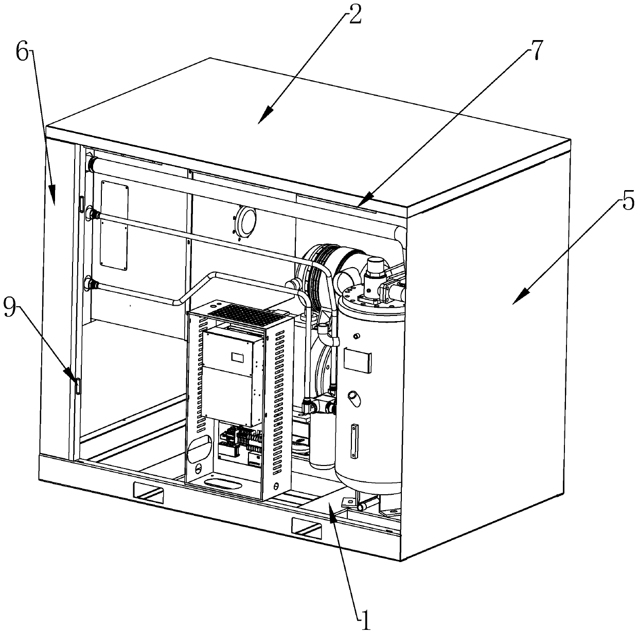
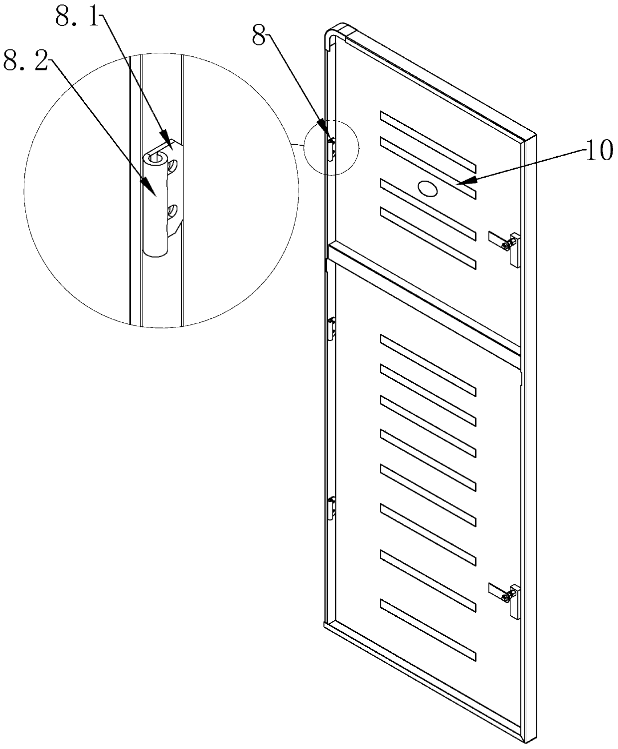
The invention discloses an air compressor box capable of achieving convection heat dissipation and noise reduction. The box comprises a bottom plate, a top cover plate, a front door plate, a rear doorplate, two side plates, four vertical frame columns and a box body frame; door hinges are arranged on the side edges of the front door plate and the rear door plate; a bolt corresponding to the doorhinge is arranged on the box body frame; the upper portion of the front door plate and the lower portion of the rear door plate are each provided with an air inlet and a fan assembly. Heat dissipationopenings are formed in the lower portion of the front door plate and the upper portion of the rear door plate, and the fan assembly comprises a driving motor and an axial flow fan blade; the axial flow fan blade comprises a hub and at least one blade body, a first flow guide groove is formed in the negative pressure face of each blade body, and each first flow guide groove comprises at least twosub-grooves formed in the radial direction of the hub at intervals. The door plate of the air compressor is convenient to mount and dismount, the cooling fans are mounted on the front door plate and the rear door plate of the air compressor box body to form convection heat dissipation, the heat dissipation effect is good, and the fans can further effectively reduce air supply noise.

Description

technical field [0001] The invention relates to the technical field of air compressors, in particular to an air compressor casing with convection heat dissipation and noise reduction. Background technique [0002] An air compressor is a machine that compresses air to generate huge gas power. It is used to propel machinery, gas or liquid and has many uses. Air compressor air pumps can be divided into electric air pumps, manual air pumps and foot-operated air pumps according to the power source. Existing air compressors emit a large amount of heat energy during operation. After a short period of operation in a confined space, the high heat will cause poor compression efficiency or shutdown. [0003] Aiming at the situation of poor efficiency, in the prior art, a fan is installed in the box to realize heat dissipation, but the blades of the conventional fan are relatively smooth, and part of the air flow is easy to form a vortex air flow under the action of centrifugal force, ...

Claims


Application Information

Patent Timeline
IPC IPC(8): F04B39/12F04B39/06F04D19/00F04D25/08F04D29/38F04D29/66E06B3/36E06B7/02E06B3/70E05D7/12
CPCE05D7/12E05D2007/126E06B3/36E06B3/70E06B7/02F04B39/066F04B39/121F04D19/002F04D25/08F04D29/386F04D29/388F04D29/666
Inventor 刘彬杨宗亮陈宇新
Owner 江西卡帕气体技术有限公司
Learn More