
Full hydraulic driving drilling machine hydraulic load-sensitive system

A technology of load-sensing and load-sensing valves, which is applied in the direction of fluid pressure actuators, mechanical equipment, servo motors, etc., can solve problems such as waste of energy, fluctuations, high oil temperature in hydraulic systems, etc., to ensure reliability and safety, Reduce heat production and energy consumption, reasonable effect of hydraulic system

Pending Publication Date: 2020-03-17
LIAONING HANSHI MACHINERY MFG CO LTD
View PDF0 Cites 3 Cited by
  • Summary
  • Abstract
  • Description
  • Claims
  • Application Information

AI Technical Summary

Problems solved by technology

[0002] Full-hydraulic drive drilling rigs play an important role in the process of open-pit ore mining. At present, most of the hydraulic systems of full-hydraulic drive drilling rigs use traditional throttling and speed regulation systems. The hydraulic system is greatly affected by load fluctuations, resulting in the operating speed of hydraulic actuators. Unstable, affecting the working performance of the drilling rig
The traditional throttling speed regulation system produces serious heat and wastes energy. At the same time, the oil temperature of the hydraulic system is too high, which affects the performance of the hydraulic system and the service life of hydraulic components.
The traditional throttling speed control system cannot adjust the speed of hydraulic actuators steplessly and quickly in real time, and cannot meet the requirements of different speeds of actuators in various working conditions of drilling rigs
Moreover, most of the current drilling rig walking systems are single-speed walking, and the walking speed is low when the drilling rig is in a long-distance transition, which increases the transition time and wastes manpower and material resources.

Method used


Image

  • Full hydraulic driving drilling machine hydraulic load-sensitive system

Examples


Embodiment Construction

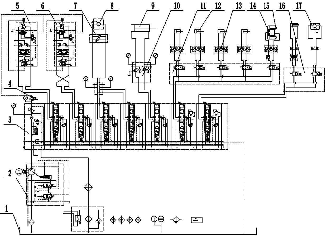
[0021] Below in conjunction with the accompanying drawings, the specific embodiments of the present invention will be further described: figure 1 In the hydraulic load-sensing system of the fully hydraulic driving drilling rig according to the present invention, the load-sensing pump 2 can absorb hydraulic oil from the hydraulic oil tank 1, and transmit the hydraulic oil to the load-sensing valve 3 through the hydraulic pipeline, and the load-sensing valve 3 can pass Control the opening direction and size of the spool, control the movement direction of the hydraulic oil and the hydraulic oil flow through the load-sensitive valve 3.

[0022] At the same time, the load-sensing valve 3 can feed back the load condition of the actuator to the load-sensing pump 2, and the load-sensing pump 2 can adjust the displacement according to the pressure signal fed back by the load-sensing valve 3, and provide the flow on demand, so as to reduce the heat generation and heat generation of the h...


PUM


Abstract

The invention relates to the technical field of surface mine machinery, in particular to a full hydraulic driving drilling machine hydraulic load-sensitive system. The speed of the actuating elementsof the sensing system can realize stepless regulation, and double speed switching can be carried out on the travelling speed to meet various working demands of a drilling machine. The full hydraulic driving drilling machine hydraulic load-sensitive system comprises a hydraulic oil tank, a load-sensitive pump, a load-sensitive valve, a travelling double-speed switching electromagnetic valve, a lefttravelling motor and a right travelling motor; the inlet of the load-sensitive pump is connected with the hydraulic oil tank; the outlet of the load-sensitive pump is connected with the inlet of theload-sensitive valve; the first-path outlet of the load-sensitive valve is connected with the left travelling motor; the second-path outlet of the load-sensitive valve is connected with the right travelling motor; the left travelling motor and the right travelling motor are used for driving the drilling machine to travel; and the travelling double-speed switching electromagnetic valve is connectedwith the displacement control port of the left travelling motor and the displacement control port of the right travelling motor.

Description

technical field [0001] The invention relates to the technical field of open-pit mining machinery, in particular to a hydraulic load-sensing system for a full-hydraulic driving drilling rig. Background technique [0002] The fully hydraulic driven drilling rig plays an important role in the open-pit ore mining process. At present, the hydraulic system of the fully hydraulic driven drilling rig mostly adopts the traditional throttle speed regulation system, which is greatly affected by the load fluctuation, resulting in the running speed of the hydraulic actuator. Unstable, affecting the working performance of the drilling rig. The traditional throttling speed control system produces serious heat and wastes energy. At the same time, the oil temperature of the hydraulic system is too high, which affects the performance of the hydraulic system and the service life of the hydraulic components. The traditional throttling speed regulation system cannot adjust the speed of hydrauli...

Claims


Application Information

Patent Timeline
Patent Type & Authority Applications(China)
IPC IPC(8): F15B11/16F15B11/04
CPCF15B11/165F15B11/04F15B2211/88F15B2211/75
Inventor 张吉平姜鹏宋海涛张铁平白爽张金龙邹伟潘洪涛贺东明吕秀梅娄群张淼
Owner LIAONING HANSHI MACHINERY MFG CO LTD
Learn More