An internal combustion engine permanent magnet magneto-rheological fan clutch and fan

A magneto-rheological and internal-combustion engine technology, applied in the field of clutches, can solve problems such as inability to automatically adjust, small maximum torque, poor heat dissipation effect, etc., and achieve the effects of avoiding easy failure, increased friction torque, and enhanced heat dissipation effect

Inactive Publication Date: 2020-11-17
CHONGQING UNIV OF TECH
View PDF18 Cites 0 Cited by
  • Summary
  • Abstract
  • Description
  • Claims
  • Application Information

AI Technical Summary

Problems solved by technology

[0006] In view of the above-mentioned deficiencies in the prior art, the purpose of the present invention is to solve the problems that the maximum value of the torque transmitted by the existing fan clutch is small, the transmission efficiency is low, the heat dissipation effect is poor, the stability is poor, and the problem that it cannot be automatically adjusted according to the real-time temperature is provided. A permanent magneto-rheological fan clutch and fan for an internal combustion engine, using permanent magnets to generate a magnetic field, so that the magneto-rheological fluid in the clutch can work without an external power supply, which improves the reliability of the clutch under complex and harsh working conditions; and through magneto-rheological The composite transmission method combining liquid, shape memory alloy spring and centrifugal friction structure effectively improves the maximum torque transmitted by the magneto-rheological clutch at high temperature, thereby ensuring the performance and stability of the clutch transmission torque and improving the heat dissipation effect of the fan

Method used


Image

  • An internal combustion engine permanent magnet magneto-rheological fan clutch and fan
  • An internal combustion engine permanent magnet magneto-rheological fan clutch and fan
  • An internal combustion engine permanent magnet magneto-rheological fan clutch and fan

Examples


Embodiment

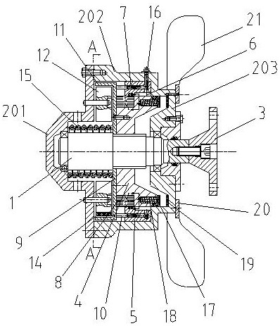
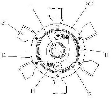
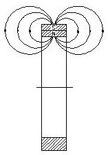
[0028] Example: see figure 1 , figure 2 as well as image 3, a permanent magnet magneto-rheological fan clutch for an internal combustion engine, comprising a drive shaft 1 , a driven housing and an input flange 3 . The driven housing includes a left end cover 201, a housing 202 and a right end cover 203 connected in sequence, wherein the inner hole of the housing 202 is a stepped hole, the section near the left end is a large diameter section, and the section near the right end is a small diameter section. section; during specific implementation, the right end cover 203 is integrally formed with the housing 202, thereby improving the stability of the entire driven housing. The driving shaft 1 is located in the driven housing, and its two ends are respectively connected to the left end cover 201 and the right end cover 203 through bearings, and the right end of the driving shaft 1 passes through the right end cover 203 and is fixedly connected to the input flange 3 . A bea...


PUM


Abstract

The invention discloses a permanent magnet magneto-rheological fan clutch of an internal combustion engine and a fan. The permanent magnet magneto-rheological fan clutch of the internal combustion engine comprises a driving shaft, a driven shell and an input flange plate; the driving shaft is sleeved with a sliding ring, and the outer side of the sliding ring is sleeved with a magnetism isolatingring; an annular groove surrounding the magnetism isolating ring by a circle is formed in the inner side of the magnetism isolating ring, and the space between the annular groove and the sliding ringis filled with magneto-rheological liquid; a plurality of oil storage holes are distributed in the left side of the magnetic isolation ring; the left end of the sliding ring is sleeved with a permanent magnet. A magnetism isolating friction plate is arranged on the left side of the sliding ring, and a piston rod is arranged on the right side of the magnetism isolating friction plate. A first shapememory alloy spring is arranged between the magnetic isolating friction plate and the left end cover. The fan comprises the permanent magnet magneto-rheological fan clutch and a fan assembly. The maximum torque transmitted by the magneto-rheological clutch can be increased, the stability of the transmission performance of the clutch at the high temperature is guaranteed, the heat dissipation effect of the fan is enhanced, the energy is saved, and the environmental protection is achieved.

Description

technical field [0001] The invention relates to the technical field of clutches, in particular to a permanent magnet magneto-rheological fan clutch and a fan of an internal combustion engine. Background technique [0002] Magneto-rheological fluid is a solid-liquid two-phase functional material whose shape and performance are constrained and controlled by an external magnetic field; it is a magnetic smart material, which is mainly composed of magnetic particles and base fluid, and is controlled by an external magnetic field. When a magnetic field is present, it exhibits the properties of Newtonian fluid; after adding a magnetic field, the viscosity of the magnetorheological fluid will change by several orders of magnitude in a very short time, showing mechanical properties similar to solids; the entire change process is rapid and continuously controllable reversible. [0003] Based on the magnetorheological effect of magnetorheological fluid, it is widely used in clutches, ...

Claims


Application Information

Patent Timeline
Patent Type & Authority Patents(China)
IPC IPC(8): F16D27/01F16D27/12
CPCF16D27/01F16D27/12
Inventor 黄金熊洋
Owner CHONGQING UNIV OF TECH
Why Eureka
Try Eureka