Motor stator and rotor iron core stamping progressive die adopting dispensing lamination and dispensing process

A technology of stator and rotor adopting points, which is applied in the field of stamping progressive die and dispensing technology of motor stator and rotor iron core, which can solve the problems of reducing the quality of the iron core, affecting the magnetic performance of the iron core, reducing the stamping production efficiency, etc., and achieving the improvement of solidification Effects of speed, improved magnetic performance, and improved reliability

Active Publication Date: 2022-07-22
JIANGYIN HUAXIN PRECISION TECH CO LTD
View PDF14 Cites 0 Cited by
  • Summary
  • Abstract
  • Description
  • Claims
  • Application Information

AI Technical Summary

Problems solved by technology

[0006] First, due to the long curing time of the glue, it may cause the iron core punches to be stacked in the tightening ring and have not yet been cured, resulting in deformation of the iron core after discharge, which affects the quality of the iron core dispensing and stacking
If the speed of stamping is artificially slowed down to wait for the glue to fully solidify before the core is discharged from the tightening ring, the efficiency of stamping production will be greatly reduced
[0007] The second is that the glue supply system of the existing glue dispensing device adopts pneumatic glue supply, which easily causes the air pressure in the glue dispensing process to be unstable, so that it is difficult to control the glue dispensing amount when dispensing the iron core. Inadequate bonding will affect the assembly and use of the iron core; too much glue will cause the glue to overflow easily and be difficult to clean. Magnetic properties
[0008] The third is that the glue inlet channel and nozzle (dispensing outlet) on the dispensing device are easy to block or pollute during use. After the blockage or pollution, its cleaning and maintenance are more troublesome, which also affects the efficiency of stamping production
[0009] Fourth, there may be oil stains on the surface of the sheet metal used to produce iron core punching sheets. In addition, when the sheet metal passes through the progressive die of the punch press, the lubricating oil on the punch press and the progressive die may contaminate the surface of the sheet metal, which will cause Reduce the firmness of the bond after lamination of iron core punching sheets, thereby reducing the quality of the iron core
[0010] Fifth, the ambient temperature of the stamping workshop used to manufacture the iron core will change, especially in the severe cold winter, the curing speed of the glue may slow down due to the low temperature, which will greatly reduce the efficiency of stamping production and may affect the curing process. strength

Method used


Image

  • Motor stator and rotor iron core stamping progressive die adopting dispensing lamination and dispensing process
  • Motor stator and rotor iron core stamping progressive die adopting dispensing lamination and dispensing process
  • Motor stator and rotor iron core stamping progressive die adopting dispensing lamination and dispensing process

Examples


Embodiment 1

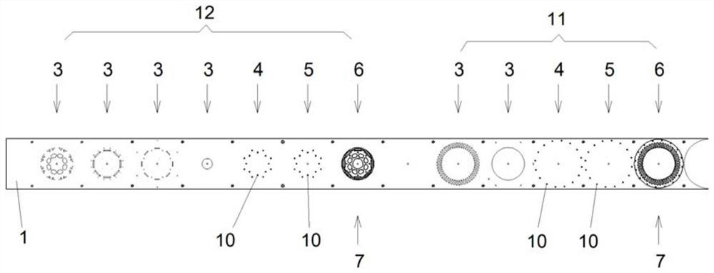
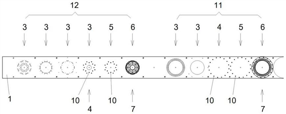
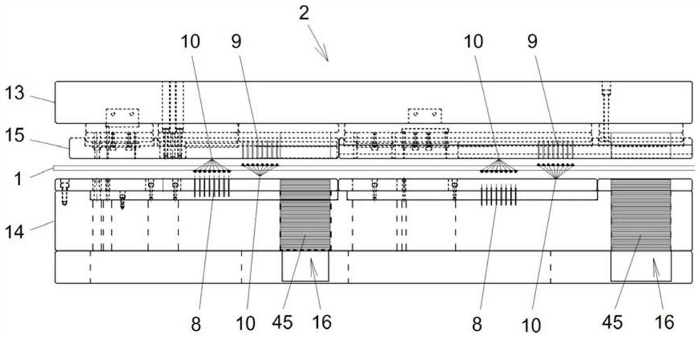
[0094] like Figures 1 to 8 Shown is an embodiment of a stamping progressive die for the stator and rotor iron core of a motor using glue-dispensing lamination, including the progressive die 2 for the stator and rotor iron core stamping of the motor sequentially arranged in accordance with the moving direction of the material strip 1. Stamping station 3, first component glue dispensing station 4, second component glue dispensing station 5 and blanking station 6, the iron core punching sheet is arranged below the blanking station 6 The automatic stacking mechanism 7, and one of the glue dispensing stations of the first component glue dispensing station 4 and the second component glue dispensing station 5 is located above the material belt 1, The other glue dispensing station is located below the material belt 1; wherein, the first component glue dispensing station 4 is provided with a device for dispersing the first component glue material to the material belt The first compon...

Embodiment 2

[0146] A glue dispensing lamination process for a stator and rotor iron core of a motor, comprising the following steps:

[0147](1) Dispensing station setting: On the stator and rotor iron core stamping progressive die 2 of the motor, according to the moving direction of the material belt 1, the stamping station 3, the first component glue dispensing station 4, and the second group are set in order. The glue dispensing station 5 and the blanking station 6 are divided, the iron core punching automatic stacking mechanism 7 is arranged below the blanking station 6, and the first component glue dispensing station 4 And one of the glue dispensing stations of the second component glue dispensing station 5 is located at the upper position of the material belt 1, and the other glue material dispensing station is located at the lower position of the material belt 1; The first-component glue dispensing station 4 is provided with a first-component glue dispensing device 8 for distributi...


PUM


Abstract

The invention discloses a motor stator and rotor iron core stamping progressive die adopting dispensing lamination and a dispensing process, and a dispensing lamination device comprises a stamping station, a first component sizing material dispensing station, a second component sizing material dispensing station and a blanking station which are arranged on the motor stator and rotor iron core stamping progressive die, an automatic iron core punching sheet stacking mechanism is arranged below the blanking station, one of the first group of sizing material dispensing stations and the second group of sizing material dispensing stations is located above the material belt, and the other one of the first group of sizing material dispensing stations and the second group of sizing material dispensing stations is located below the material belt; a first component glue dispensing device is arranged on the first component glue dispensing station, and a second component glue dispensing device is arranged on the second component glue dispensing station; in the first component sizing material and the second component sizing material, one component sizing material is a main sizing material, and the other component sizing material is a catalyst. According to the invention, the quality and the production efficiency of motor stator and rotor iron core dispensing lamination are improved.

Description

technical field [0001] The invention relates to the technical field of manufacturing a stator and rotor iron core of a motor for a new energy electric vehicle and a precision motor stator and rotor iron core with high requirements on motor performance, in particular to a stamping progressive die for a motor stator and rotor iron core using glue dispensing and lamination, and Dispensing process. Background technique [0002] The stator and rotor iron core of the motor includes the stator iron core of the motor and the rotor iron core of the motor, both of which are formed by stacking silicon steel sheets (punch sheets). Silicon steel sheets are usually stamped on a punching machine using a stamping progressive die. Usually, the stamping progressive die is provided with an upper die plate, a lower die plate and a stripper plate located between the upper die plate and the lower die plate, a plurality of punches are installed on the upper die plate, and a corresponding position...

Claims


Application Information

Patent Timeline
Patent Type & Authority Applications(China)
IPC IPC(8): H02K15/02H02K15/12
CPCH02K15/02H02K15/12Y02T10/64
Inventor 郭斌周宜存刘大伟赵来远
Owner JIANGYIN HUAXIN PRECISION TECH CO LTD
Why Eureka
Try Eureka