
A production process of air suspension bearing high-speed frequency conversion motor impeller

A variable frequency motor and air suspension technology, applied in the field of variable frequency motor impellers, can solve the problems of unable to achieve automatic output, unable to continuously produce fan blades, reduce production output, etc., to improve quality and assembly efficiency, high degree of automation, reduce product quality effect

Active Publication Date: 2020-11-06
深圳市贵庭机电设备有限公司
View PDF7 Cites 0 Cited by
  • Summary
  • Abstract
  • Description
  • Claims
  • Application Information

AI Technical Summary

Problems solved by technology

[0005] The purpose of the present invention is to address the deficiencies of the prior art, by setting the fan base positioning work to complete the automatic tightening of the fan base, positioning, and then using the welding work of the first blade and the welding work of the remaining blades to weld the fan base in sequence The finished fan blades are unscrewed and automatically output through the fan blade output work, thus solving the technical problem that the automatic output cannot be realized after the fan blades are assembled, which leads to the non-continuous production of fan blades and reduces the production output

Method used

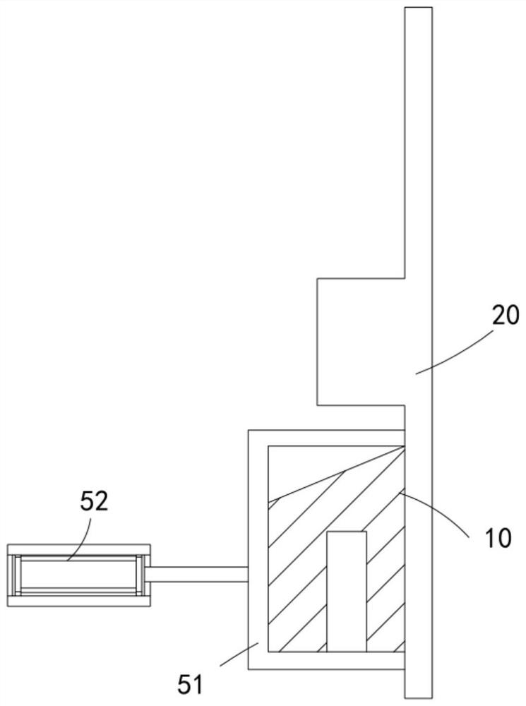

Image

  • A production process of air suspension bearing high-speed frequency conversion motor impeller
  • A production process of air suspension bearing high-speed frequency conversion motor impeller
  • A production process of air suspension bearing high-speed frequency conversion motor impeller

Examples


Embodiment 1

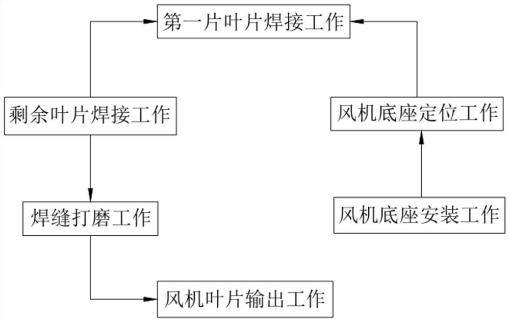
[0085] Such as figure 1 As shown, a production process of an air suspension bearing high-speed variable frequency motor impeller, including:

[0086] Step 1: Install the fan base. First, manually place the fan base on the sliding frame. Then, the three-claw manipulator 151 clamps the center of the fan base 20 and rotates it by 90°. Then, the telescopic tube 152 is extended to send the fan base 20 to On the sub-set shaft 1311 in the area of ​​the feeding station 100;

[0087] Step 2, the fan base is positioned, the starting motor 125 rotates intermittently, and the sub-axis 121 rotates from the loading station 100 to the welding station 400, the gear a rotates under the action of the arc-shaped rack a1321, and the gear a is synchronized Drive the screw rod 1324 to rotate on the sub-shaft 121, the nut 1323 drives the pressure rod 1316 to move toward the sub-sleeve shaft 1311, and push the sliding block 1314 outward to tighten the fan base 20;

[0088] Step 3, the welding work ...

Embodiment 2

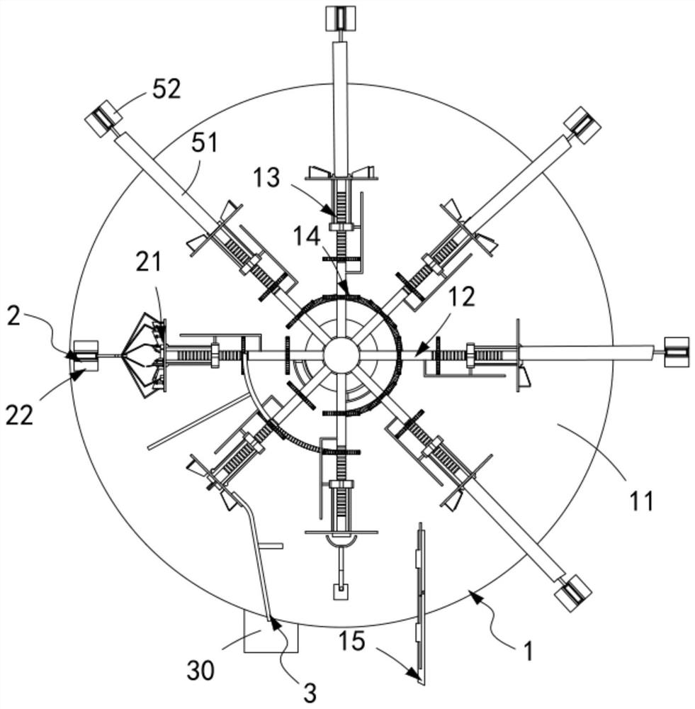
[0104] Such as figure 2 , Figure 7 As shown, an air suspension bearing high-speed variable frequency motor impeller production equipment includes:

[0105]Assembling device 1, described assembling device 1 comprises support table 11, the loading assembly 12 that is arranged on described support table 11, the tightening assembly 13 that is arranged on described feeding assembly 12, is used for driving feeding assembly 12 to complete Several groups of blades 10 are uniformly uploaded to the switching assembly 14 and the seat assembly 15 is automatically installed on the blades 10 to the feeding assembly 12;

[0106] Grinding device 2, said grinding device 2 includes several sets of hair removal assemblies 21 that are evenly arranged and each group is slidably arranged between two adjacent blades 10 after welding, and is used to drive several groups of hair removal assemblies 21 to move synchronously The drive assembly 22; and

[0107] An output device 3, the output device 3...

Embodiment 3

[0145] Such as Figure 19 , Figure 18 As shown, the parts that are the same as or corresponding to those in the first embodiment are marked with the corresponding reference numerals in the second embodiment. For the sake of brevity, only the differences from the second embodiment will be described below. The difference between this embodiment three and embodiment two is:

[0146] further, such as Figure 19 , Figure 18 As shown, the hair removal assembly 21 includes:

[0147] A connection block 211, the connection block 211 is slidably arranged on the support table 11 and located at the center between any two blades 10; and

[0148] The control piece 212, the control piece 212 is arranged in pairs on both sides of the connection block 211 and is respectively polished corresponding to the welded part of the blade 10, which includes a spring b213 fixedly connected with the connection block 211, and the spring b213 The other end of b213 is fixedly connected to the vertically...


PUM


Abstract

The invention relates to an air suspension bearing high-speed variable-frequency motor impeller production process. The process comprises the steps that 1, a draught fan base is installed, firstly, the draught fan base is manually placed on a sliding frame, then a three-jaw manipulator clamps a center of the draught fan base and rotates 90 degrees, and then, a telescopic pipe extends, and the draught fan base is conveyed to a split sleeve shaft in a feeding station area; 2, the draught fan base is positioned; 3, welding work of a first blade is performed, when a split shaft rotates to a welding station from a feeding station, the blade is positioned on the draught fan base through a limiting frame, then a welding hand carries out the welding work of the first blade, and after welding is completed, a horizontal pushing piece resets; 4, the welding work of the first blade is performed; 5, weld joint grinding work is performed; and 6, fan blades are output. Technical problems that after the fan blades are assembled, automatic output cannot be achieved, then the fan blades cannot be continuously produced, and a production yield is reduced are solved.

Description

technical field [0001] The invention relates to the technical field of variable-frequency motor impellers, in particular to a production process for high-speed variable-frequency motor impellers for air suspension bearings. Background technique [0002] Wind turbine blades, referred to as fan blades, are key components of wind turbines. The number of fan blades of a wind turbine is generally three. When rotating in the air, the weight of each blade is required to be equal to the moment relative to the center of gravity of the hub, so that the balance of the blades can be ensured when rotating. However, under the existing production process conditions of fan blades, due to various factors, such as the weight of the blade core material, size deviation, and other factors in the specific implementation process, which restrict the production process of the blades, the weight and The moments relative to the hub's center of gravity are balanced in the initial stages. [0003] The...

Claims


Application Information

Patent Timeline
Patent Type & Authority Patents(China)
IPC IPC(8): B23P15/04
CPCB23P15/04
Inventor 张长森曹枫
Owner 深圳市贵庭机电设备有限公司
Learn More