
Targeted induction and directional energy composite three-dimensional forming device and method

A technology of three-dimensional shaping and targeting induction, which is applied in coating devices, manufacturing auxiliary devices, additive manufacturing, etc., to achieve the effects of reducing equipment costs, increasing interlayer bonding strength and tissue uniformity, and improving directional energy absorption rate

Pending Publication Date: 2020-03-24
杭州德迪智能科技有限公司
View PDF0 Cites 0 Cited by
  • Summary
  • Abstract
  • Description
  • Claims
  • Application Information

AI Technical Summary

Problems solved by technology

At present, in the field of additive manufacturing, in response to the urgent need to further improve the 3D printing performance of directed energy scanning devices, there is still a lack of a solution that is reasonable, has good material adaptability, high energy utilization, and can effectively constrain the curing reaction within directed energy scanning. 3D Shaping Methods for Regions

Method used


Image

  • Targeted induction and directional energy composite three-dimensional forming device and method
  • Targeted induction and directional energy composite three-dimensional forming device and method
  • Targeted induction and directional energy composite three-dimensional forming device and method

Examples


Embodiment

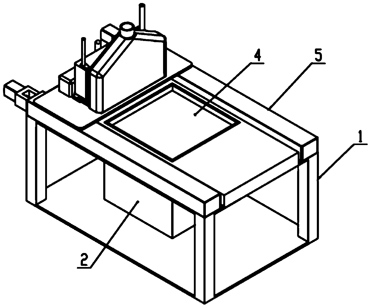
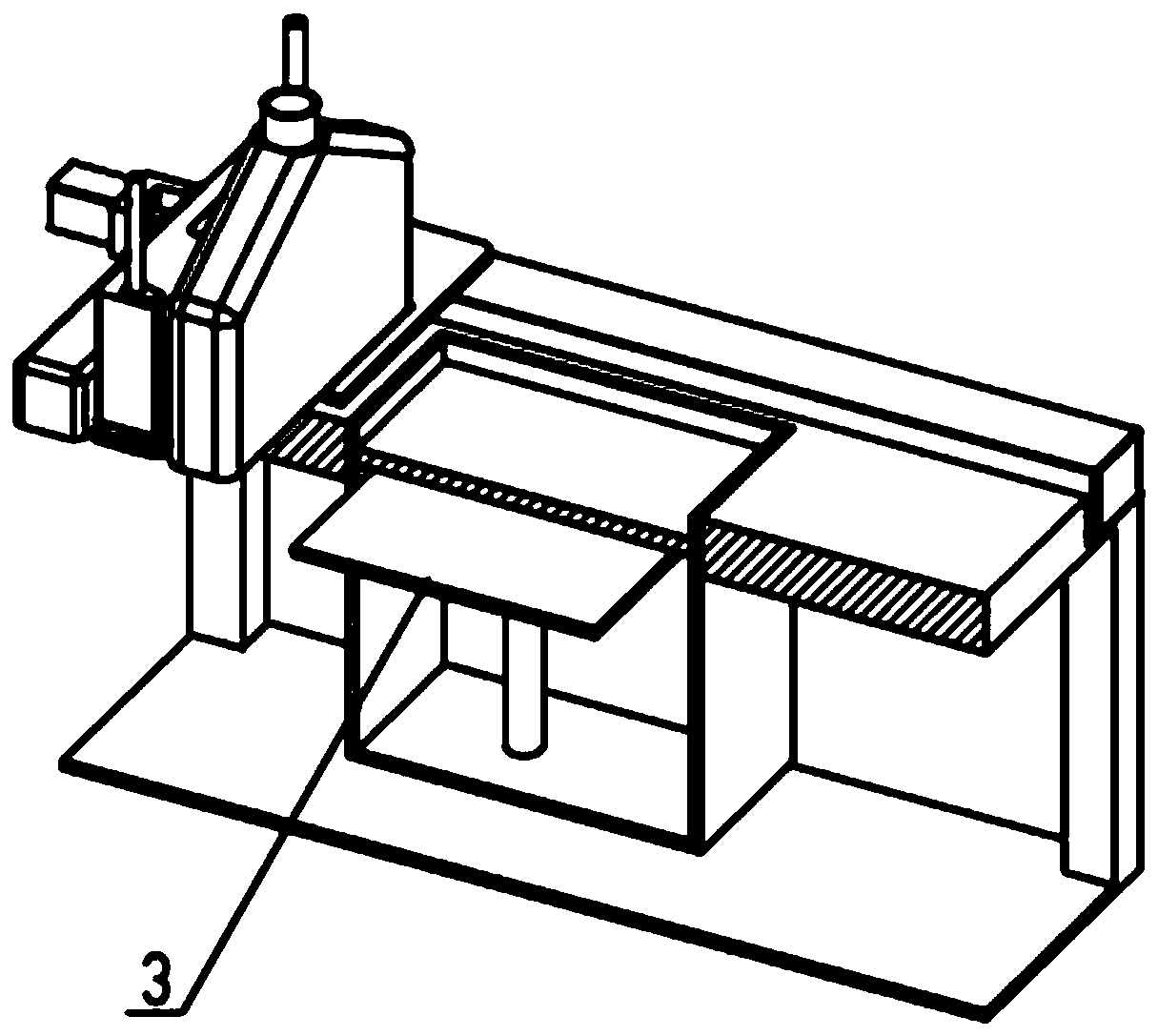
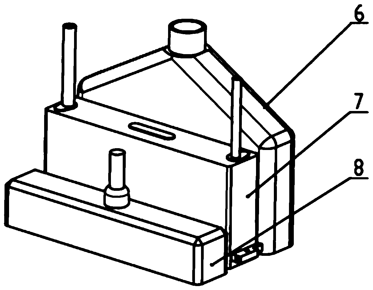
[0023] A target induction and directed energy composite three-dimensional forming device, such as Figure 1-3 As shown, there is a forming groove 2 on the rigid frame 1. There is a lifting platform 3 inside the forming groove 2. There is a forming substrate 4 on the top of the lifting platform 3. The edge of the forming substrate 4 slides and seals with the inner wall of the forming groove 2. The lifting platform 3 can drive the forming substrate. 4 Move up and down and position in the forming tank 2; there is a linear module 5 on the rigid frame 1, and a liquid / powder spreading component 6, an inducer injection component 7, and a directed energy scanning component 8 are mounted on the moving platform of the linear module 5; The module 5 drives the liquid / powder spreading assembly 6, the inducer spraying assembly 7, and the directed energy scanning assembly 8 to translate over the opening of the forming groove 2, so that the liquid / powder spreading assembly 6 can spread the liqui...


PUM


Abstract

The invention relates to a targeted induction and directional energy composite three-dimensional forming device. The device comprises a rigid frame, a forming groove is formed in the rigid frame, a lifting platform is arranged in the forming groove, a forming substrate with the edge in sliding seal fit with the inner wall of the forming groove is arranged at the top of the lifting platform, and the lifting platform can drive the forming substrate to move up and down and be positioned in the forming groove. A linear module is arranged on the rigid frame, a liquid / powder laying assembly, an inducer spraying assembly and a directional energy scanning assembly are sequentially arranged on a linear module moving platform, and the linear module can drive the assemblies to horizontally move abovethe opening of the forming groove. According to the targeted induction and directional energy composite three-dimensional forming device and method, directional energy is adopted to accurately irradiate a to-be-cured area of a liquid / powder material interface, an inducer is adopted to constrain energy behaviors of the directional energy in the to-be-cured area, the curing forming effect is good,the material utilization rate is high, the energy utilization rate is high, and the targeted induction and directional energy composite three-dimensional forming device can be applied and popularizedin various types of three-dimensional printers.

Description

technical field [0001] The invention relates to the field of three-dimensional printing, in particular to a target induction and directed energy composite three-dimensional forming device and method. Background technique [0002] The rapid development of advanced manufacturing technology is promoting the full penetration of 3D printing equipment based on directed energy scanning devices into the traditional manufacturing field. According to different forming methods, 3D printing equipment is mainly divided into: Fused Deposition Modeling (FDM), Polymer Injection Forming (PolyJet), Laser Stereolithography (SLA), Laser Selective Melting Forming (SLM), Laser Selective Sintering Forming ( SLS), electron beam direct forming (EBDM) and other types, they generally have a similar "layer-by-layer accumulation" three-dimensional forming process, that is, through the directional deposition of the melt extrusion head, the micro-nozzle array, or the directional scanning of the liquid by ...

Claims


Application Information

Patent Timeline
IPC IPC(8): B29C64/20B29C64/10B29C64/205B29C64/264B29C64/268B29C64/30B29C64/393B33Y10/00B33Y30/00B33Y40/00B33Y50/02
CPCB29C64/20B29C64/10B29C64/205B29C64/264B29C64/268B29C64/30B29C64/393B33Y10/00B33Y30/00B33Y40/00B33Y50/02
Inventor 俞红祥应华庞伟王康恒
Owner 杭州德迪智能科技有限公司
Learn More