Gas flow regulating valve driven by phase change material based on micro electro mechanical system

A technology of micro-electromechanical systems and phase-change materials, which is applied in valve details, valve devices, mechanical equipment, etc., can solve the problem of excessive response time of micro-shape memory alloy valves, high driving voltage of micro-piezoelectric ceramic valves, and flow regulation modules. Weight, volume limitations and other issues, to achieve the effect of compact structure, simple structure, micro-flow control

Inactive Publication Date: 2020-03-24
SHANGHAI JIAO TONG UNIV +1
View PDF7 Cites 2 Cited by
  • Summary
  • Abstract
  • Description
  • Claims
  • Application Information

AI Technical Summary

Problems solved by technology

[0006] 1. The flow regulation module of conventional size has limitations in terms of weight and volume, which cannot meet the requirements of miniaturization;
[0007] 2. The process of micro solenoid valve based on MEMS is relatively complicated;
[0008] 3. The driving voltage of micro piezoelectric ceramic valve based on MEMS is too high;
[0009] 4. The micro-electromechanical system-based micro-shape memory alloy valve has too long response time

Method used


Image

  • Gas flow regulating valve driven by phase change material based on micro electro mechanical system
  • Gas flow regulating valve driven by phase change material based on micro electro mechanical system
  • Gas flow regulating valve driven by phase change material based on micro electro mechanical system

Examples


Embodiment Construction

[0049] The present invention will be described in detail below in conjunction with specific embodiments. The following examples will help those skilled in the art to further understand the present invention, but do not limit the present invention in any form. It should be noted that those skilled in the art can make several changes and improvements without departing from the concept of the present invention. These all belong to the protection scope of the present invention.

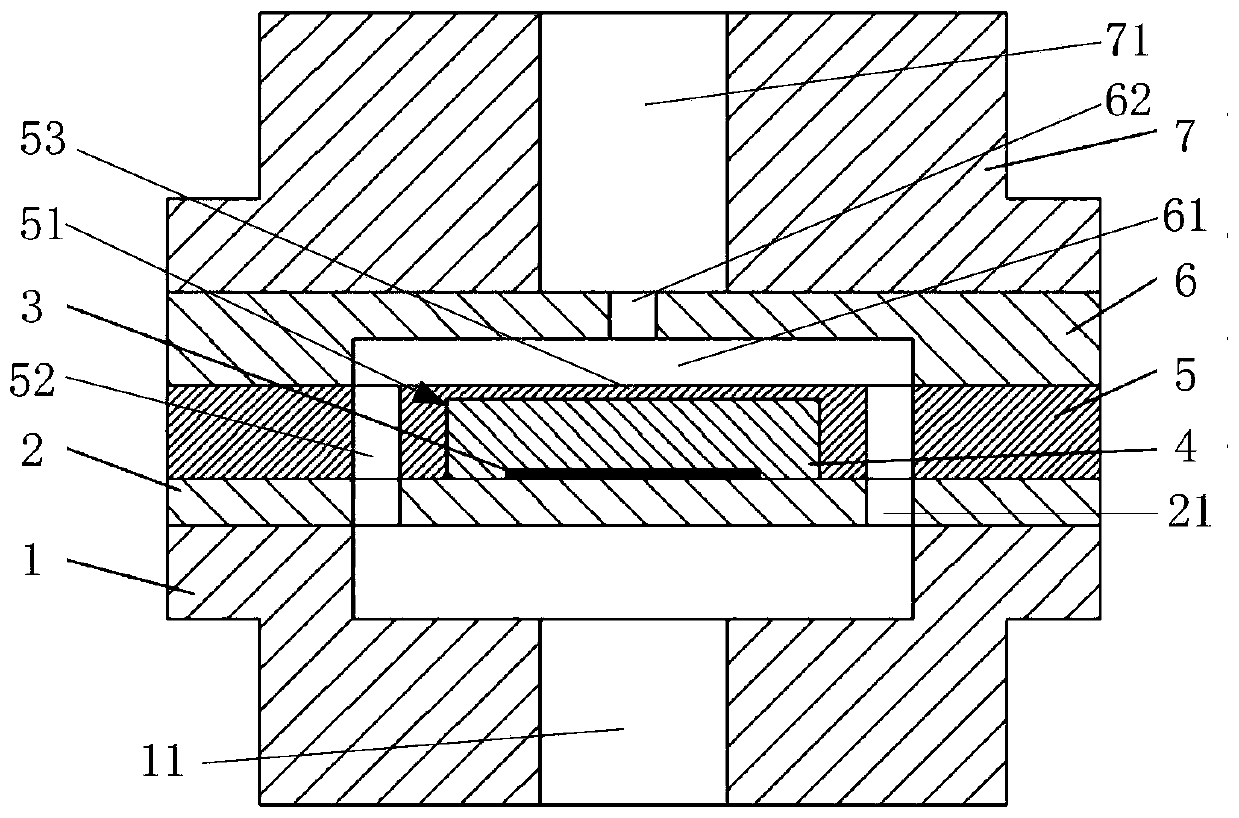
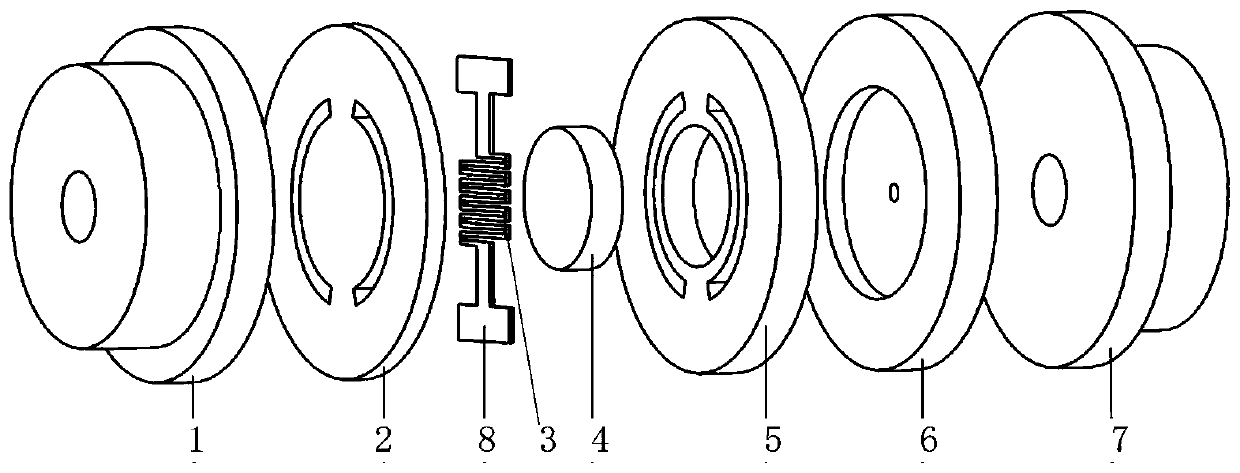
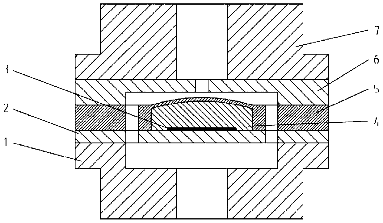
[0050] According to the gas flow regulating valve driven by a micro-electro-mechanical system based on a phase-change material provided by the present invention, such as figure 1 As shown, it includes a base 1, a heating sheet 2, a heater 3, a phase change material 4, a deformation sheet 5, an outlet sheet 6, a valve cover 7 and an electrode 8, and the valve cover 7, the outlet sheet 6, the deformation sheet 5, The phase change material 4, the heater 3, the heating sheet 2, and the base 1 are sequential...


PUM


Abstract

The invention provides a gas flow regulating valve driven by a phase change material based on a micro electro mechanical system. The valve comprises a base, a heating sheet, a heater, a phase-change material, a deformation sheet, an outlet sheet and an electrode. The outlet sheet, the deformation sheet, the phase-change material, the heater, the heating sheet and the base are connected in sequence. A base through hole is arranged in the base. A heating sheet through hole is arranged in the heating sheet. A deformation sheet groove and a deformation sheet through hole are arranged in the deformation sheet. A control space and a flow hole connected with the control space are arranged in the outlet sheet. The base through hole, the heating sheet through hole, the deformation sheet through hole, the control space and the flow hole are successively connected. The heater is powered on and heated to make the phase change material expand so that the deformation sheet is driven to elastically deform in a direction close to the flow hole, and control of a gas flow is achieved. The valve is simple in process, small in size, short in response time and small in control voltage, and automatic flow control is achieved.

Description

technical field [0001] The invention relates to the technical field of gas flow regulating valves, in particular to a gas flow regulating valve driven by phase change materials based on micro-electromechanical systems. Background technique [0002] The electric propulsion system has the advantages of high specific impulse, light weight, and less working fluid consumption, and has been widely used on satellite platforms in various countries. The application of space electric propulsion technology has gradually shifted from controlling geostationary orbit position maintenance to satellite transfer orbit change after satellite rocket separation, orbit position maintenance after satellite entry, momentum wheel unloading, and deorbiting. . Changes in space missions require the electric propulsion system to have the capability of multi-mode and variable thrust. With the help of the flow regulation module, the electric propulsion system can realize multi-mode adjustment of the xen...

Claims


Application Information

Patent Timeline
Patent Type & Authority Applications(China)
IPC IPC(8): F16K31/64
CPCF16K31/005
Inventor 王平阳赵星霖杭观荣戴佳李林
Owner SHANGHAI JIAO TONG UNIV
Why Eureka
Try Eureka