Electron beam scanning method, refractory metal member and electron beam selective melting device

An electron beam scanning and electron beam melting technology, applied in the field of additive manufacturing, can solve the problems of warping deformation, low scanning speed, and large local temperature gradient of the section of the part to be melted, so as to improve the defects of poor fusion and prevent warping. The effect of uniform deformation and thermal stress distribution

Active Publication Date: 2020-03-27
西安赛隆增材技术股份有限公司
View PDF8 Cites 4 Cited by
  • Summary
  • Abstract
  • Description
  • Claims
  • Application Information

AI Technical Summary

Problems solved by technology

Due to the very low scanning speed in the melting stage, the local temperature gradient of the cross-section of the part to be melted becomes relatively large, so the fused part on the surface of the p

Method used


Image

  • Electron beam scanning method, refractory metal member and electron beam selective melting device
  • Electron beam scanning method, refractory metal member and electron beam selective melting device
  • Electron beam scanning method, refractory metal member and electron beam selective melting device

Examples


Embodiment Construction

[0035] Example embodiments will now be described more fully with reference to the accompanying drawings. Example embodiments may, however, be embodied in many forms and should not be construed as limited to the examples set forth herein; rather, these embodiments are provided so that this disclosure will be thorough and complete and fully convey the concept of example embodiments to those skilled in the art. The described features, structures, or characteristics may be combined in any suitable manner in one or more embodiments.

[0036] In addition, the drawings are only schematic illustrations of embodiments of the present invention and are not necessarily drawn to scale. The same reference numerals in the drawings denote the same or similar parts, and thus repeated descriptions thereof will be omitted. Some of the block diagrams shown in the drawings are functional entities and do not necessarily correspond to physically or logically separate entities.

[0037] As describ...


PUM


Abstract

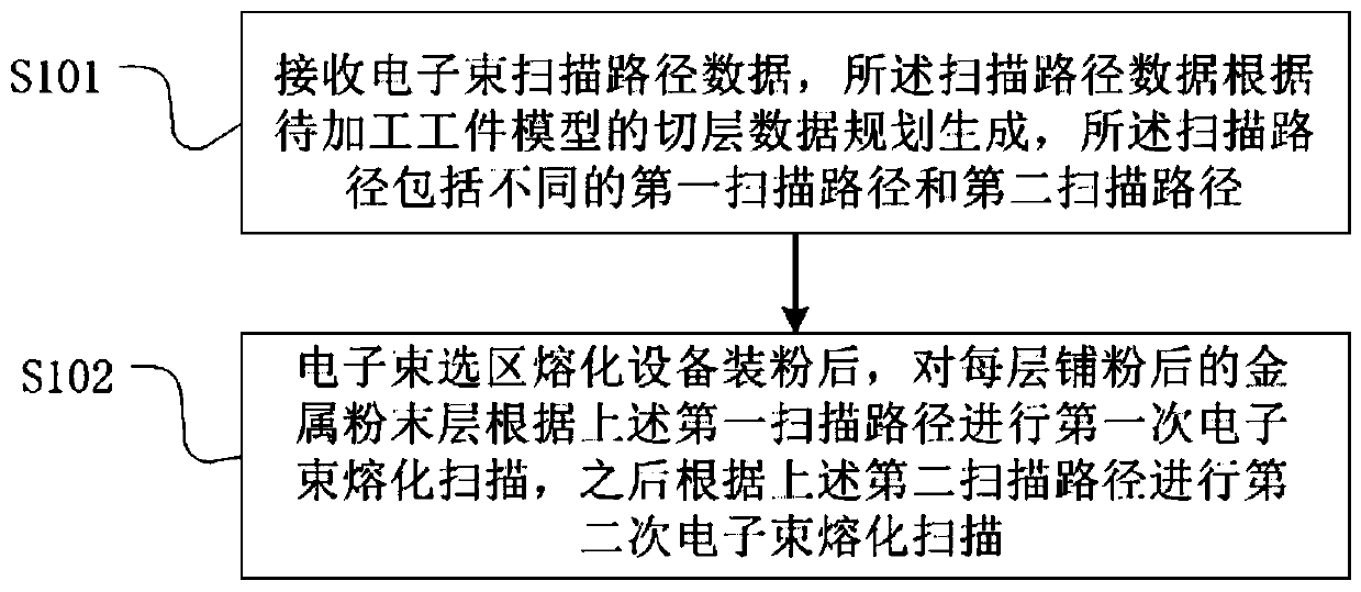
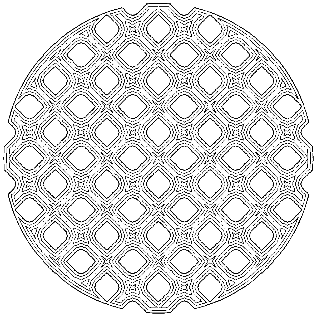
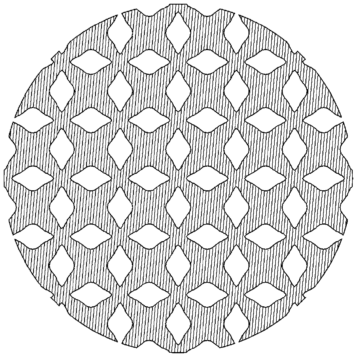
An embodiment of the invention relates to an electron beam scanning method, a refractory metal member and an electron beam selective melting device. The electron beam scanning method includes the steps of receiving electron beam scanning path data, wherein the scanning path data are generated by planning according to slice data of a to-be-processed workpiece model and comprise a first scanning path and a second scanning path which are different; and after the electron beam selective melting device is filled with powder, conducting first electron beam melting scanning on a metal powder layer obtained powder paving according to the first scanning path, and then conducting second electron beam melting scanning according to the second scanning path. By means of the embodiment, the two different scanning paths are used for conducting electron beam selective melting scanning on the metal powder layer by using the two different scanning paths, on one aspect, thermal stress distribution is more uniform, and part layer warpage and deformation are not prone to being caused; and on the other hand, the metal powder layer is subjected to two times of electron beam selective melting scanning insequence, and therefore the defect of poor fusion of part layers is overcome to a certain extent.

Description

technical field [0001] Embodiments of the present invention relate to the technical field of additive manufacturing, and in particular to an electron beam scanning method, a refractory metal component, and electron beam selective melting equipment. Background technique [0002] High melting point metals with a melting point higher than 1650°C, such as tungsten, tantalum, molybdenum, niobium, hafnium, chromium, vanadium, zirconium and titanium, tungsten, etc., and alloys formed by adding other elements based on these metals are called refractory metals. [0003] Before the mid-1940s, refractory products were mainly produced by powder metallurgy. From the late 1940s to the early 1960s, due to the development of aerospace technology and atomic energy technology, the application of metallurgical technologies such as consumable electric arc furnaces and electron bombardment furnaces promoted the use of refractory metals that can be heated at 1093-2360 °C or higher. Development o...

Claims


Application Information

Patent Timeline
IPC IPC(8): B22F3/105B33Y10/00B33Y30/00B33Y50/02
CPCB22F3/003B33Y10/00B33Y30/00B33Y50/02B22F10/00B22F12/17B22F10/28B22F10/366Y02P10/25
Inventor 全俊涛赵培朱纪磊赵小欢弋阳闫利强王伟向长淑
Owner 西安赛隆增材技术股份有限公司
Why Eureka
Try Eureka