System and method for detecting out-of-band rejection capability of ultraviolet imager
A technology of out-of-band suppression and ultraviolet imaging, which is applied in the direction of testing optical performance, etc., can solve the problems of unsuitable detection of out-of-band suppression performance of ultraviolet imagers, high personnel requirements, and high design and processing precision, so as to facilitate widespread application and environmental personnel The effect of low requirements and low detection environment requirements
- Summary
- Abstract
- Description
- Claims
- Application Information
AI Technical Summary
Problems solved by technology
Method used
Image
Examples
Embodiment 1
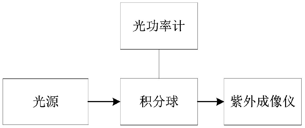
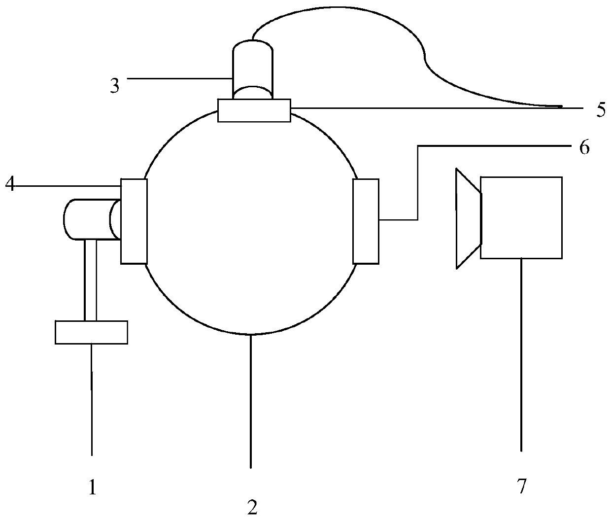
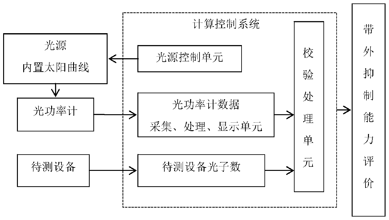
[0042] This embodiment provides a detection system for the out-of-band suppression capability of an ultraviolet imager, such as Figure 1-2 As shown, it includes a light source 1, an integrating sphere 2, an optical power meter 3 and a calculation control system.
[0043]The light source 1 provides optical signals with continuous wavelengths in the 280-1100nm band, and the spectrum of the light source includes ultraviolet rays, visible light and infrared rays. The light source includes a solar simulator and two ultraviolet band LED light sources (wavelengths are 310 + 5nm, 365 + 5nm).
[0044] The integrating sphere 2 is provided with a light entrance 4 and two light exits 5, 6, the light entrance 4 is connected to the light source 1, one light exit 5 is used to connect with the device under test 7, and the other light exit Port 6 is connected to the optical power meter. The caliber of the light outlet 5 is greater than 50mm.
[0045] The light source passes through the i...
Embodiment 2
[0056] This embodiment provides a method for detecting the out-of-band suppression capability of an ultraviolet imager using the detection system described in Embodiment 1, which includes the steps:
[0057] 1) Turn on the device under test;
[0058] 2) Turn on the detection system, select the test standard, and after the light source is stable, place the optical power meter at one of the light outlets of the integrating sphere, and check the light source stability and light source curve through the optical power meter to ensure that the light source remains consistent during each detection;
[0059] 3) Place the device under test at the other light outlet of the integrating sphere; observe the response of the device under test to the light source signal and the number of photons;
[0060] 4) The verification processing unit selects the photon number evaluation standard according to the optical power meter data and the photon number value of the device, and evaluates the out-o...
Embodiment 3
[0063] This embodiment provides a method for using the detection system described in Embodiment 1 to measure the response performance of an ultraviolet sensor to sunlight.
[0064] The light source uses a xenon lamp close to sunlight and an ultraviolet LED as a light source. After passing through the integrating sphere, two paths of light are emitted, one for reference light and one for test light. The optical power meter measures the reference optical power, the UV sensor to be tested is placed at the light outlet of the test light, and the rear end of the sensor outputs a response electrical signal.
PUM
 Abstract
Description
Claims
Application Information
 - R&D
- Intellectual Property
- Life Sciences
- Materials
- Tech Scout
- Unparalleled Data Quality
- Higher Quality Content
- 60% Fewer Hallucinations
Browse by: Latest US Patents, China's latest patents, Technical Efficacy Thesaurus, Application Domain, Technology Topic, Popular Technical Reports.
© 2025 PatSnap. All rights reserved.Legal|Privacy policy|Modern Slavery Act Transparency Statement|Sitemap|About US| Contact US: help@patsnap.com


