Variable frequency vibration method capable of shortening response time and vibration actuator

A technology of variable frequency vibration and response time, applied in piezoelectric effect/electrostrictive or magnetostrictive motors, generators/motors, electrical components, etc. and other problems to achieve the effect of shortening the start-stop response time

Active Publication Date: 2020-03-27
NANJING UNIV OF AERONAUTICS & ASTRONAUTICS
View PDF7 Cites 0 Cited by
  • Summary
  • Abstract
  • Description
  • Claims
  • Application Information

AI Technical Summary

Problems solved by technology

In contrast, the application of virtual buttons and pressure-sensitive buttons is increasing. Compared with physical buttons, virtual buttons have many advantages, such as: easy to program, and the form and position can be set at will, which improves the humanization of system operation; improves the use of equipment. Lifespan, the mechanical structure of the physical buttons will have performance degradation and waterproof and dustproof problems with use, but the virtual buttons have a fatal shortcoming: no hand feeling, because the virtual buttons are all set on the touch screen, so users will have a feeling when using them. If there is no certain visual or auditory feedback, the user cannot be sure whether the button is pressed; so engineers use vibration as the feedback of the virtual button, and today's vibration tactile feedback has achieved a false effect, such as Apple ( The pressure-sensitive touch panel of the latest notebook computer of Apple Inc) and Magic Trackpad 2, an independent touch panel product, are a good example of implementation; traditional touch panels generally adopt a rocker structure, such as figure 1 As shown in 1a, the touch panel is fixed by a hinge mechanism, and the other end is connected to the tactile switch. Pressing the touch panel will trigger the tactile switch, which will produce a "step" pressing feel and the sound of button pressing; Obviously, this structure cannot be pressed down when pressing the top of the touch panel, that is, near the fixed end of 1a in the figure, which greatly reduces the user experience; 1b in the figure shows Apple's pressure-sensitive touch panel Schematic diagram of the structure. The structure is equipped with pressure sensors at the four corners of the touch panel. When the user's pressing force reaches the set threshold, the linear vibration motor fixed under the touch panel will be activated to output a certain waveform of vibration, so as to simulate the pressure. Tactile sensation (this is the vibration-like phenomenon in tactile psychology. In short, it uses a series of modulated

Method used


Image

  • Variable frequency vibration method capable of shortening response time and vibration actuator
  • Variable frequency vibration method capable of shortening response time and vibration actuator
  • Variable frequency vibration method capable of shortening response time and vibration actuator

Examples


Embodiment 1

[0073] Based on the above, the first thing to do in this application is to derive the theoretical formula of the traveling wave, as follows:

[0074] Step 1: According to the existing traveling wave synthesis theory of annular ultrasonic motor, write the two-phase standing wave formula for synthesizing traveling waves, and analyze the relationship between the phase difference of the two-phase standing waves and the running direction of the synthesized traveling waves ;

[0075] The existing standing wave formula is:

[0076] W 1 (θ,t) = Asinnθcos2πft (1)

[0077]

[0078] By superimposing the above formula (1) and formula (2), the synthetic traveling wave formula (3) can be obtained:

[0079]

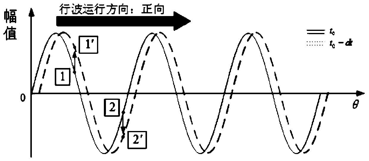
[0080] From formula (3), it can be found that,

[0081] When the two-phase standing wave time phase difference , formula (3) becomes forward traveling wave formula (4):

[0082] W=sin(nθ-ωt) (4)

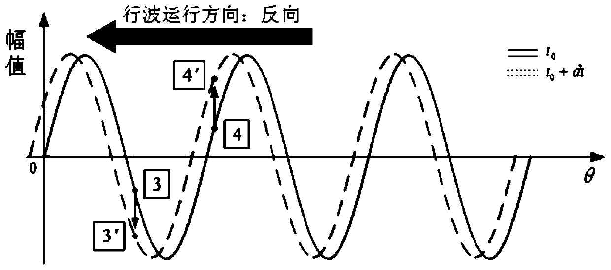
[0083] When the phase difference between two standing wave times , the for...

Embodiment 2

[0125] Then apply the beat traveling wave theory obtained above to the circular traveling wave rotating ultrasonic motor, and use this theory to design a new type of vibration actuator, a vibration actuator designed based on the above frequency conversion vibration method, Figure 6 As shown, this design is only a schematic representation, the size can be large or small (D: 5-60mm, H: 3-5mm), and can be embedded in various systems that require vibration and tactile feedback; such as handheld smart devices, outdoor large-scale touch screen display devices, and wearable haptic feedback devices.

[0126] Including the hollow shaft 3, sleeved on the hollow shaft 3 Figure 8 In the stator elastomer ceramic sheet assembly shown, the bottom surface of the vibration output interface 1 is fixed on the hollow shaft 3, and the hollow shaft 3 is fixedly connected with the vibration output interface 1 through screws. At the same time of locking, the surface of the annular stator elastic b...


PUM


Abstract

The invention relates to a variable frequency vibration method capable of shortening response time and a vibration actuator. The vibration actuator comprises a hollow shaft, a vibration output interface and an annular stator elastomer, the hollow shaft is sleeved with the annular stator elastomer, the vibration output interface is fixedly arranged at the top of the hollow shaft through screws, thehollow shaft locks the annular stator elastomer in the axial direction, and meanwhile the annular stator elastomer generates pre-pressure to abut against the vibration output interface; a friction material is laid on the contact surface of the annular stator elastomer and the vibration output interface; and partitioned polarized piezoelectric ceramics are laid on the end face, away from the vibration output interface, of the annular stator elastomer. A plastic wear-resistant sleeve is arranged between the stator elastomer and the hollow shaft, and the plastic wear-resistant sleeve is also arranged on the hollow shaft in a sleeving manner. The problem that a traditional motor is slow in response time can be solved, and the response time of the vibration actuator designed based on the vibration method is greatly prolonged.

Description

technical field [0001] The invention relates to a frequency conversion vibration method capable of shortening response time and a vibration actuator, belonging to the field of ring ultrasonic motors. Background technique [0002] Today's handheld smart devices on the market are all dominated by touch screens with large sizes and high proportions. Device manufacturers are gradually eliminating physical buttons. In contrast, the application of virtual buttons and pressure-sensitive buttons is increasing. Compared with physical buttons, virtual buttons have many advantages, such as: easy to program, and the form and position can be set at will, which improves the humanization of system operation; improves the use of equipment. Lifespan, the mechanical structure of the physical buttons will have performance degradation and waterproof and dustproof problems with use, but the virtual buttons have a fatal shortcoming: no hand feeling, because the virtual buttons are all set on the ...

Claims


Application Information

Patent Timeline
IPC IPC(8): H02N2/06H02N2/08
CPCH02N2/06H02N2/08
Inventor 杨淋马成成任韦豪
Owner NANJING UNIV OF AERONAUTICS & ASTRONAUTICS
Why Eureka
Try Eureka