Crushing device for treating impurities filtered out from sewage

A crushing equipment and filtration technology, which is applied in grain processing, chemical/physical processes, mixers with rotating stirring devices, etc., can solve the problems of difficulty in meeting crushing requirements, difficult fermentation of filtrate, long fermentation time, etc., to achieve Simple structure, good effect and high crushing efficiency

Inactive Publication Date: 2020-03-31
寇金臣
0 Cites 3 Cited by

AI-Extracted Technical Summary

Problems solved by technology

[0004] Although there is not much dirt in domestic sewage, most of them are rice grains, melon peels, and domestic organic garbage. These dirt can be completely reused, and the amount of accumulation is large. It is a huge waste, and most of these impurities cannot be directly reused. Although these filtered substances can be used for direct biogas fermentation, without treatment, the fermentation t...

Method used

Embodiment two: present embodiment is further improved as last embodiment: be provided with ball at longitudinal push rod 11 bottoms, thus avoid rotating plate 14 that contacts with rotating plate 14 durin...

Abstract

The invention discloses a crushing device for treating impurities filtered out from sewage, and relates to crushing equipment. The crushing device comprises a crushing box, wherein a motor is fixedlyconnected with and arranged at the top part of the crushing box; a horizontal rotating shaft is fixedly connected with and arranged at the output end of the motor; a driving bevel gear is fixedly connected with and arranged on the horizontal rotating shaft; a driven shaft is rotatably connected with and arranged at the top part of the crushing box; a driven bevel gear is fixedly connected with andarranged at the top part of the driven shaft and is engaged with the driving bevel gear; a universal coupling is fixedly connected with and arranged at the bottom part of the driven shaft; a crushingshaft is connected with and arranged below the universal coupling; crushing blades are fixedly connected with and arranged at the bottom part of the crushing shaft; a cam is fixedly connected with and arranged at the outer side of the horizontal rotating shaft; and a longitudinal ejector rod is slidably connected with and arranged at the upper left part of the crushing box. The crushing device provided by the invention is simple in structure and convenient to use, can fully and thoroughly crush impurities filtered out from sewage in the crushing box when in use, facilitates more sufficient reutilization of the filtered-out impurities, improves the recovery rate of energy, has good effect and high crushing efficiency, and is worthy of popularization.

Application Domain

Rotary stirring mixersTransportation and packaging +2

Technology Topic

Electric machineryCam +6

Image

  • Crushing device for treating impurities filtered out from sewage
  • Crushing device for treating impurities filtered out from sewage
  • Crushing device for treating impurities filtered out from sewage

Examples

  • Experimental program(2)

Example Embodiment

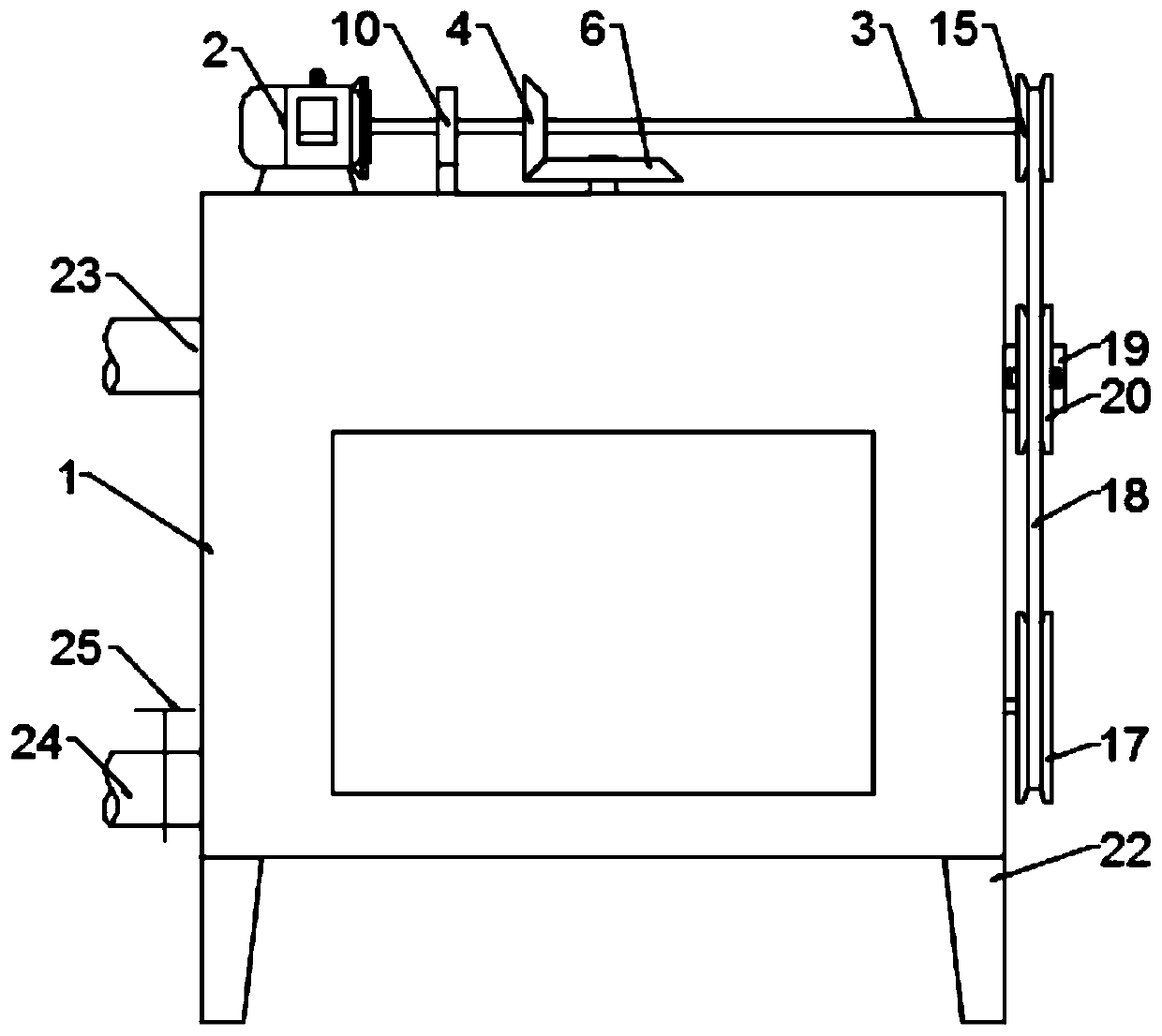
[0024] Example 1: Please refer to Figure 1-4 , a crushing device for treating impurities filtered out of sewage, comprising a crushing box 1, a motor 2 is fixedly connected to the top of the crushing box 1, a horizontal shaft 3 is fixedly connected to the output end of the motor 2, and a driving bevel gear is fixedly connected to the horizontal shaft 3 4. The top of the crushing box 1 is rotatably connected with a driven shaft 5, and the top of the driven shaft 5 is fixedly connected with a driven bevel gear 6, and the driven bevel gear 6 meshes with the driving bevel gear 4;
[0025] When in use, add the impurities filtered out of the sewage into the crushing box 1, turn on the motor 2, the rotation of the motor 2 drives the rotation of the horizontal shaft 3, the rotation of the horizontal shaft 3 drives the rotation of the active bevel gear 4, and then drives the driven shaft 5 through the driven bevel gear 6 turn;
[0026] The bottom of the driven shaft 5 is fixedly connected with a universal coupling 7, the bottom of the universal coupling 7 is connected with a crushing shaft 8, and the bottom of the crushing shaft 8 is fixedly connected with a crushing blade 9;
[0027] The rotation of the driven shaft 5 can drive the crushing shaft 8 to rotate through the universal coupling 7, and the impurities are crushed by the crushing blade 9. Since the impurities are filtered out in the sewage, most of them are paste after crushing. For drying, water can be added appropriately to make it a paste. Due to the different sedimentation coefficients, larger particles such as sand and gravel will settle to the bottom during crushing, and some impurities are difficult to be completely crushed;
[0028] The outer side of the horizontal rotating shaft 3 is fixedly connected with a cam 10, the upper left side of the crushing box 1 is slidably connected with a longitudinal ejector rod 11, the middle part of the longitudinal ejector rod 11 is fixedly connected with a positioning block 12, and the upper part of the positioning block 12 is fixedly connected with a spring 13, and the spring 13 is connected with the The crushing box 1 is fixedly connected, the upper end of the longitudinal ejector rod 11 is offset against the cam 10, the upper end of the crushing shaft 8 is fixedly connected with a rotating plate 14, and the lower end of the longitudinal ejector rod 11 is offset against the rotating plate 14;
[0029] The rotation of the cam 10 drives the longitudinal ejector rod 11 to move up and down, and then drives the crushing shaft 8 to displace through the rotating plate 14, and the crushing blade 9 can crush different positions;
[0030] The right end of the horizontal rotating shaft 3 is fixedly connected with a driving pulley 15, the bottom right side of the crushing box 1 is rotatingly connected with a side rotating shaft 16, and the outer end of the side rotating shaft 16 is fixedly connected with a driven pulley 17, and the driving pulley 15 and the driven pulley 17 is socketed with transmission belt 18, and the rear of crushing box 1 right side is fixedly connected with electric telescopic rod 19, and the output end of electric telescopic rod 19 is connected with tension pulley 20 in rotation, and tension pulley 20 cooperates with transmission belt 18, so The inner end of the side rotating shaft 16 is fixedly connected with a spiral mixing blade 21;
[0031] Intermittently open the electric telescopic rod 19, the electric telescopic rod 19 drives the tension pulley 20 to move, so that the transmission belt 18 is tightened, thereby driving the spiral mixing blade 21 to rotate, so that the filtrate is fully mixed, and the crushing blade 9 is used for more thorough crushing .
[0032] The bottom of the crushing box 1 is fixedly connected with a supporting base 22 symmetrically.
[0033] The spring 13 is sleeved on the outside of the longitudinal push rod 11 .
[0034] The crushing blades 9 are provided with 1-3 groups, preferably, the crushing blades 9 are provided with 2 groups.
[0035] The top left side of the crushing box 1 is fixedly connected with a feed pipe 23, the bottom left side of the crushing box 1 is fixedly connected with a discharge pipe 24, and the middle part of the discharge pipe 24 is fixedly connected with a valve 25. Whether the pulverized matter flows out.
[0036] The diameter of the driving bevel gear 4 is greater than the diameter of the driven bevel gear 6 .
[0037] The spring 13 is a metal tension spring.
[0038] The motor 2 and the electric telescopic rod 19 are respectively electrically connected to the power supply through a switch.
[0039] The diameter of the driving pulley 15 is smaller than that of the driven pulley 17 .

Example Embodiment

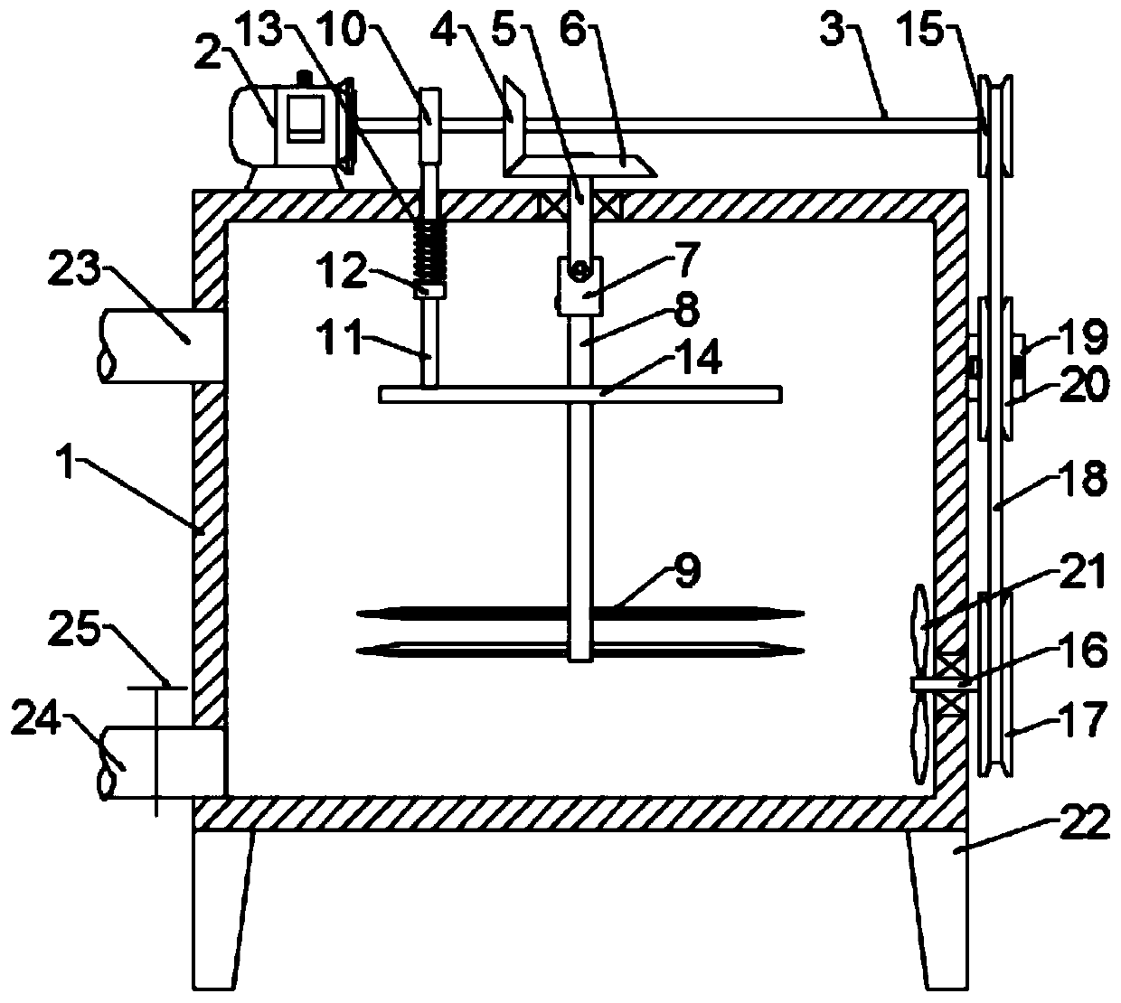
[0040] Embodiment 2: This embodiment is a further improvement of the previous embodiment: a ball is provided at the bottom of the longitudinal push rod 11, thereby avoiding damage to the rotating plate 14 caused by contact with the rotating plate 14 during the vertical movement of the vertical pushing rod 11. , A transparent observation window can be fixed on the crushing box 1, which is convenient for intuitive understanding of the crushing process.
[0041]The working principle of the present invention is: when in use, add the impurities filtered out of the sewage into the crushing box 1, turn on the motor 2, the rotation of the motor 2 drives the horizontal shaft 3 to rotate, the rotation of the horizontal shaft 3 drives the rotation of the active bevel gear 4, and then passes through the driven cone The gear 6 drives the driven shaft 5 to rotate, and the rotation of the driven shaft 5 can drive the crushing shaft 8 to rotate through the universal coupling 7, and crush the impurities through the crushing blade 9. Since the impurities are filtered out in the sewage, more If the filtrate is dry, you can add water appropriately to make it a paste. Due to the different sedimentation coefficients, larger particles such as sand and gravel will settle to the bottom during crushing, and some impurities are difficult to be completely crushed. The rotation of the cam 10 drives the longitudinal ejector rod 11 to move up and down, and then the rotating plate 14 drives the crushing shaft 8 to displace, the crushing blade 9 can crush different positions, and the electric telescopic rod 19 is intermittently opened, and the electric telescopic rod 19 drives the tension pulley 20 The movement makes the transmission belt 18 tight, thereby driving the spiral mixing blade 21 to rotate, so that the filtrate is fully mixed, and the pulverizing blade 9 is used to pulverize more thoroughly.

PUM

no PUM

Description & Claims & Application Information

We can also present the details of the Description, Claims and Application information to help users get a comprehensive understanding of the technical details of the patent, such as background art, summary of invention, brief description of drawings, description of embodiments, and other original content. On the other hand, users can also determine the specific scope of protection of the technology through the list of claims; as well as understand the changes in the life cycle of the technology with the presentation of the patent timeline. Login to view more.

Similar technology patents

Body condition measuring device

InactiveUS20050234351A1simple structure
Owner:DENSO CORP

Magnetic cooling apparatus and control method thereof

ActiveUS20130180263A1simple structure
Owner:SAMSUNG ELECTRONICS CO LTD

Dual-Drivetrain of Power-Assist Vehicle

InactiveUS20100181130A1enhance uphill momentumsimple structure
Owner:CHOU WEN CHENG

Classification and recommendation of technical efficacy words

  • Simple structure
  • easy to use

Sharing system for air-conditioning coat

InactiveCN107440179ASimple structureeasy to wear
Owner:QINGDAO HAIER AIR CONDITIONER GENERAL CORP LTD

Feeding device of sorter of batteries plate

InactiveCN101357717ASimple structurecooperate well
Owner:NANJING NORMAL UNIVERSITY

Emergency parachuting device and method for multiple-rotor unmanned aerial vehicle

InactiveCN103895870Aavoid aircraft crashSimple structure
Owner:SOUTH CHINA AGRI UNIV +1

Laser assisted total joint arthroplasty

InactiveUS20090234360A1easy to use
Owner:ALEXANDER VLADIMIR

Enclosure for a portable hemodialysis system

ActiveUS20090114582A1easy to use
Owner:DEKA PROD LLP
Why Eureka
Try Eureka