Bag electric dust remover for belt conveyor head and tail

A belt conveyor and dust collector technology, applied in electrostatic effect separation, chemical instruments and methods, dispersed particle filtration, etc., can solve problems affecting the safe, reliable and stable operation of dust removal devices, increasing operating costs, and occupying a large space. , to achieve the effect of significant energy saving, low operating cost and low operating resistance

Pending Publication Date: 2020-03-31
江苏乾云环保工程有限公司
View PDF0 Cites 0 Cited by
  • Summary
  • Abstract
  • Description
  • Claims
  • Application Information

AI Technical Summary

Problems solved by technology

There are many types of such dust removal devices, but they are composed of various types of dust collectors and fans, pipelines, dust suction hoods, material guide troughs and other components. In order to meet the needs of network resistance and wind speed, the fan must have sufficient air volume and wind pressure. Therefore, the energy consumption (electricity and water) is relatively high, the volume is large, the space is large, and the maintenance is large, which affects the safety of the dust removal device. , reliable and stable operation
[0003] At the same time, various material conveying equipment in some industries such as metallurgy, building materials and refractory materials have long been dominated by belt conveyors. The dust removal device of the belt conveyor is a separate dust removal system. When dust removal is required, the belt conveyor The fan and the main fan of the dust collector need to start two fans at the same time, which increases the power of the main fan of the dust collector, increases the operating cost, causes unnecessary waste, and has a certain impact on the environment

Method used


Image

  • Bag electric dust remover for belt conveyor head and tail
  • Bag electric dust remover for belt conveyor head and tail
  • Bag electric dust remover for belt conveyor head and tail

Examples


Embodiment Construction

[0018] The present invention will be described below in conjunction with the accompanying drawings.

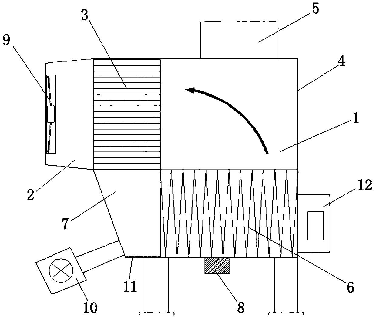
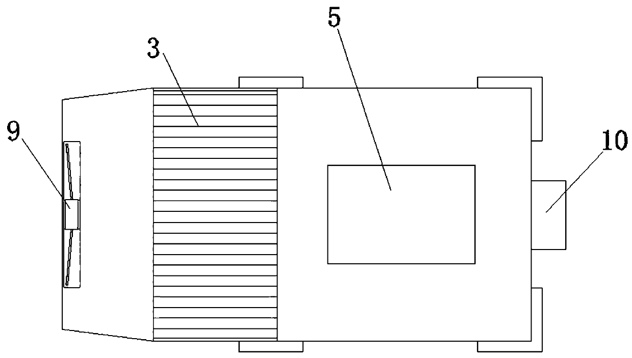
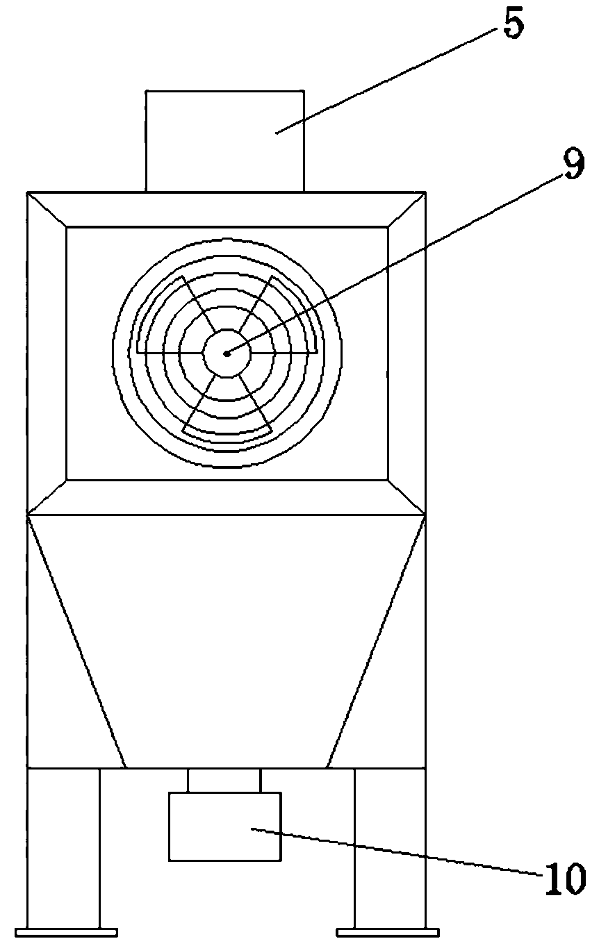
[0019] like Figure 1-3 As shown, the bag electrostatic precipitator used for the head and tail of the belt conveyor includes a dust collector housing 1, and the upper side of the dust collector housing 1 is sequentially provided with an air outlet channel 2, a plate-type high-voltage electrostatic field 3, and a mixed air Road 4; a high-voltage pulse generator 5 is provided above the mixing air duct 4, and a high-efficiency pre-filter bag 6 is provided below the mixing air duct 4; an air inlet channel 7 is provided on one side of the high-efficiency pre-filter bag 6, and the high-efficiency pre-filter bag The bottom of 6 is provided with automatic dust removal oscillator 8; the air outlet of air outlet channel 2 is provided with exhaust fan 9; An automatic ash unloading plate 11 is also provided at the bottom of the dust collector; a controller 12 is provided on the outside ...


PUM


Abstract

The bag electric dust remover for the head and the tail of the belt conveyor comprises a dust remover shell, and an air outlet channel, a plate type high-voltage electrostatic field and a mixed air channel are sequentially arranged on one side of the upper portion in the dust remover shell. A high-voltage pulse generator is arranged above the mixed air duct, and an efficient pre-filtering bag is arranged below the mixed air duct; an air inlet channel is formed in one side of the efficient pre-filtering bag, and an automatic ash removal oscillator is arranged below the efficient pre-filtering bag; an exhaust fan is arranged at an air outlet of the air outlet channel; an air blower is arranged on the outer side of the air inlet channel and communicates with the air inlet channel through an air pipe, and an automatic ash discharging plate is further arranged at the bottom of the air inlet channel; and a controller is arranged on the outer side of the dust remover shell. The bag electric dust remover provided by the invention is compact in structure, reasonable in design, convenient to manufacture, stable in operation for a long time, low in emission, low in operation resistance, longin filter bag service life, remarkable in energy conservation and low in operation cost.

Description

technical field [0001] The invention belongs to the related field of dust waste gas treatment equipment, and in particular relates to a bag electrostatic precipitator used for the head and tail of a belt conveyor. Background technique [0002] At present, in the coal conveying system of most coal-fired power plants, the pulverized coal is sent to the coal-fired boiler through multiple coal conveying belts. At the end of the belt, it is gradually transferred to the boiler by analogy. The junction of the two belts is called a transfer station, where the coal dust rapidly spreads and flies when the belts are running, which not only seriously pollutes the work site and the surrounding environment, but also wastes a large amount of coal powder. Therefore, dust removal treatment is necessary. The dust removal device of the coal transfer station is an essential equipment for every coal-fired power plant. There are many types of such dust removal devices, but they are composed of ...

Claims


Application Information

Patent Timeline
Patent Type & Authority Applications(China)
IPC IPC(8): B03C3/017B03C3/011B01D46/04
CPCB01D46/04B03C3/011B03C3/017
Inventor 史乾徐香云徐卫中
Owner 江苏乾云环保工程有限公司
Why Eureka
Try Eureka