Eureka AIR delivers breakthrough ideas for toughest innovation challenges, trusted by R&D personnel around the world.

Single-cylinder glue injection mechanism of injection molding machine

An injection molding machine and injection technology, applied in the field of single-cylinder injection mechanism of injection molding machine, can solve the problems of difficult assembly, complex structure, low injection pressure, etc. Effect

Pending Publication Date: 2020-03-31
佛山市顺德区震德精密机械有限公司
View PDF0 Cites 3 Cited by
  • Summary
  • Abstract
  • Description
  • Claims
  • Application Information

AI Technical Summary

Problems solved by technology

[0004] 1. The parts of injection cylinder head N3, transmission sleeve N4, injection piston rod N6 and transmission shaft N7 are expensive, and a large number of solid bars are required to be processed in the processing of parts, and the processing accuracy is required to be high
[0005] 2. The injection pressure is low, and in the mechanism, the area where the injection pressure is generated can be seen figure 2 Position B, and the seal between the injection cylinder head N3, the transmission sleeve N4 and the transmission shaft N7 is prone to leakage, which will affect the injection force
[0006] 3. The plasticization is unstable. In this mechanism, the oil motor N1 is connected to the transmission sleeve N4, the transmission sleeve N4 is connected to the transmission shaft N7, and the transmission shaft N7 is connected to the screw N8, so that the torque between the oil motor N1 and the screw N8 is too long , leading to low mechanical efficiency and high motor load during the transmission process, which in turn affects the stability of plasticization
[0007] 4. Assembly and maintenance are difficult. Because there are a large number of concentric sleeve parts and sealing parts in the mechanism, assembly is extremely difficult. The technical requirements for assemblers are relatively high. great
[0008] 5. The space of the mechanism is large, so the frame under the injection platform needs to be made longer, which increases the cost of the whole machine
[0009] 6. The structure is complex, there are many moving pairs, and it is difficult to achieve sufficient lubrication between parts, so the risk of parts wear is high and maintenance is difficult

Method used


Image

  • Single-cylinder glue injection mechanism of injection molding machine
  • Single-cylinder glue injection mechanism of injection molding machine
  • Single-cylinder glue injection mechanism of injection molding machine

Examples


Embodiment 1

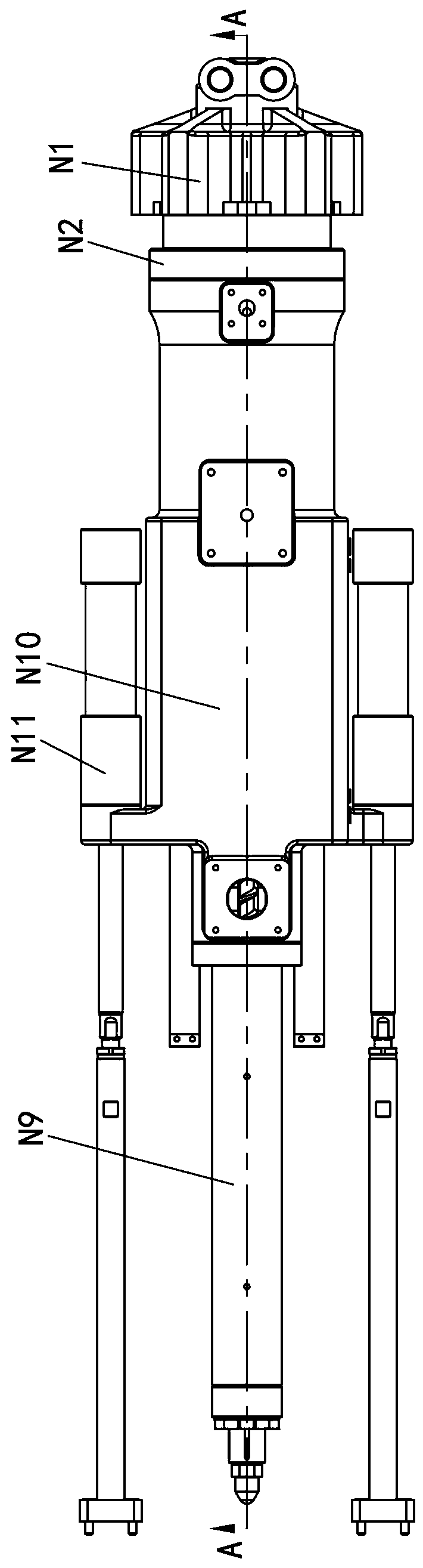
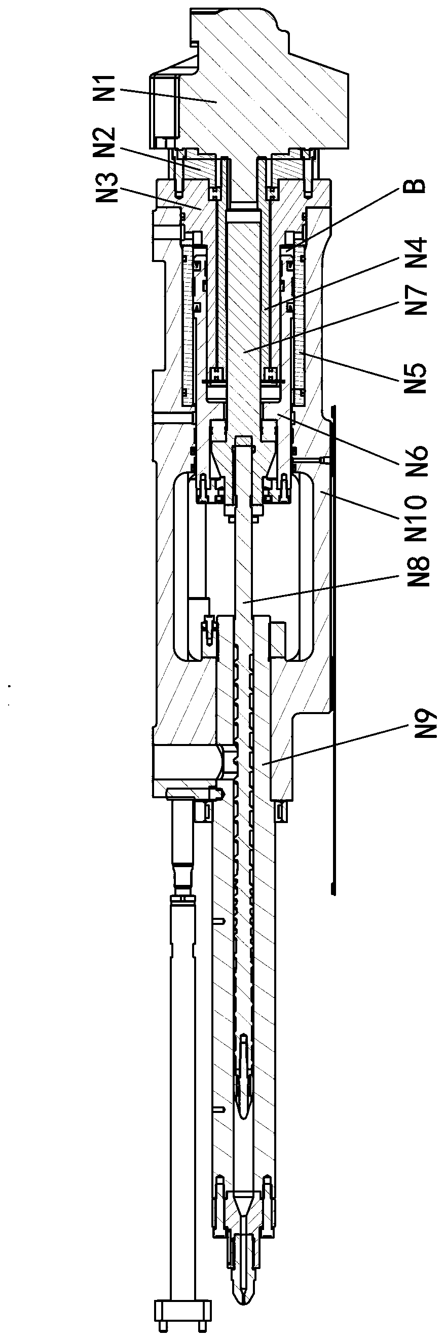
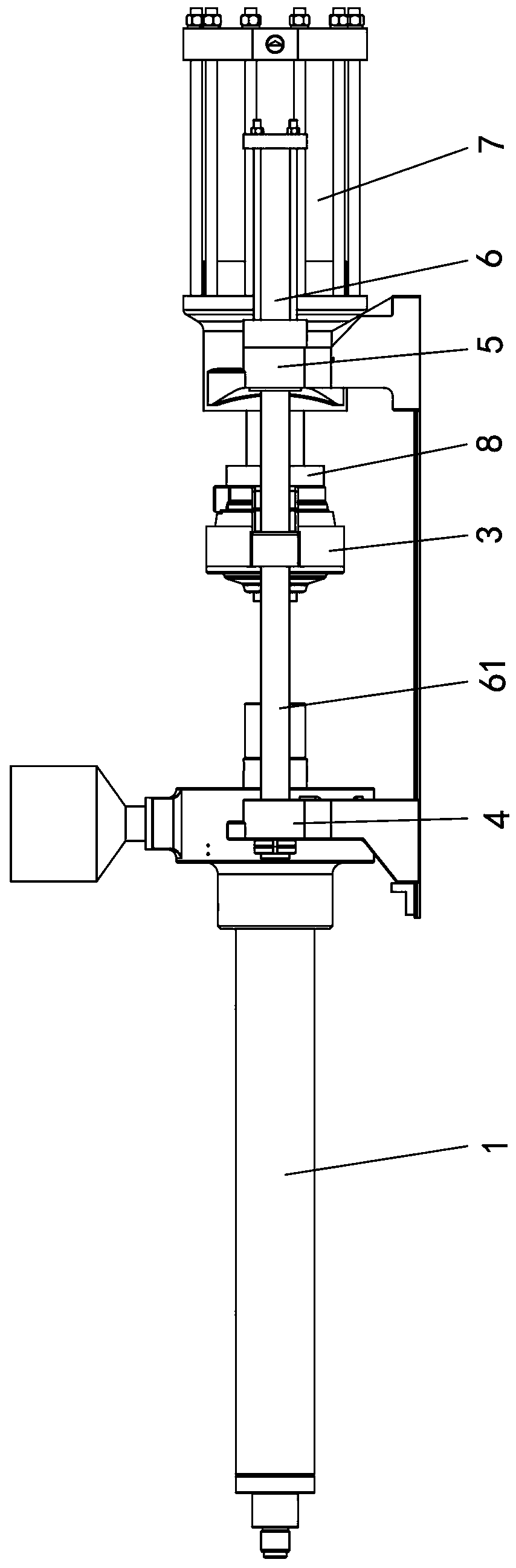
[0025] Embodiment one, see Figure 3-4 As shown, a single-cylinder injection mechanism of an injection molding machine includes a barrel 1, an injection screw 2, a melt motor 3, an injection head plate 4, an injection tail plate 5, a guide post 61, an injection cylinder 6 and an injection cylinder. Glue cylinder 7.

[0026] In this embodiment, there are two shooting cylinders 6 , and the telescoping ends of the shooting cylinders 6 constitute the guide post 61 .

[0027] Wherein, the telescopic end of the injection cylinder 6 passes through the injection tail plate 5 and the injection head plate 4 and is locked and fixed by a limit pin and a nut, and the injection tail plate 5 is slidably connected with the telescopic end of the injection cylinder 6,

[0028] The tail of the gun barrel 1 is fixed on the glue injection head plate 4, the melt glue motor 3 is arranged between the glue injection head plate 4 and the glue injection tail plate 5, and between the telescopic ends of ...


PUM


Abstract

The invention discloses a single-cylinder glue injection mechanism of an injection molding machine. The single-cylinder glue injection mechanism comprises a gun barrel, a glue injection lead screw, aglue melting motor, a glue injection head plate, a glue injection tail plate, a guide pillar, an injection displacement oil cylinder and a glue injection oil cylinder; the glue injection head plate isfixedly connected with the front end of the guide pillar; the glue injection tail plate is slidably connected with the rear end of the guide pillar; the tail part of the gun barrel is fixed to the glue injection head plate; the glue melting motor is arranged on the guide pillar; one end of the glue injection lead screw is connected with the glue melting motor; the other end of the glue injectionlead screw passes through the glue injection head plate and is arranged in the gun barrel; the glue injection oil cylinder is fixed to the glue injection tail plate; the telescopic end of the glue injection oil cylinder pushes the glue melting motor to move on the guide pillar; the injection displacement oil cylinder is fixed to the glue injection tail plate; and the injection displacement oil cylinder drives the guide pillar to move. The movement of the gun barrel is controlled by the injection displacement oil cylinder, and the movement of the glue injection lead screw and the glue melting motor is controlled by the glue injection oil cylinder, so that the structure of the glue injection oil cylinder is simplified, the requirement is low, and the injection pressure is improved; the gluemelting motor is guided to move by the guide pillar, so that the injection stability is improved; the overall structure is simple and reasonable; and the machining, assembly and maintenance are easy.

Description

technical field [0001] The invention relates to the technical field of injection molding equipment, in particular to a single-cylinder injection mechanism of an injection molding machine. Background technique [0002] The injection mechanism of the existing injection molding machine, the current single cylinder injection structure is quite complicated, its structure is to connect the melting glue motor and the screw rod through the transmission shaft, and the transmission shaft cooperates with the transmission sleeve and is installed in the injection cylinder. See the specific structure figure 1 and figure 2 As shown, the mechanism parts include oil motor N1 (melting motor), motor flange N2, injection cylinder head N3, transmission sleeve N4, injection cylinder body N5, injection piston rod N6, transmission shaft N7, screw N8 , barrel N9, injection seat N10 and shooting cylinder N11. Its assembly method: fix the material pipe group, the injection cylinder and the melt mo...

Claims


Application Information

Patent Timeline
Patent Type & Authority Applications(China)
IPC IPC(8): B29C45/54B29C45/58
CPCB29C45/54B29C45/58
Inventor 苏嘉朗陈伟吴嘉星石长城梁健民
Owner 佛山市顺德区震德精密机械有限公司
Why Eureka
Eureka Blog
Learn More