
Industrial waste treatment device for environmental protection

A technology for industrial waste and treatment devices, applied in combustion methods, lighting and heating equipment, indirect carbon dioxide emission reduction, etc., can solve the problems of reducing the quality of waste incineration, insufficient waste incineration, etc. The effect of improving incineration quality

Inactive Publication Date: 2020-03-31
吕玲
View PDF1 Cites 2 Cited by
  • Summary
  • Abstract
  • Description
  • Claims
  • Application Information

AI Technical Summary

Problems solved by technology

The above-mentioned patent also has the following disadvantages: the garbage is not crushed before incineration, which may easily lead to insufficient incineration of garbage and reduce the quality of incineration of garbage

Method used


Image

  • Industrial waste treatment device for environmental protection
  • Industrial waste treatment device for environmental protection
  • Industrial waste treatment device for environmental protection

Examples


Embodiment 1

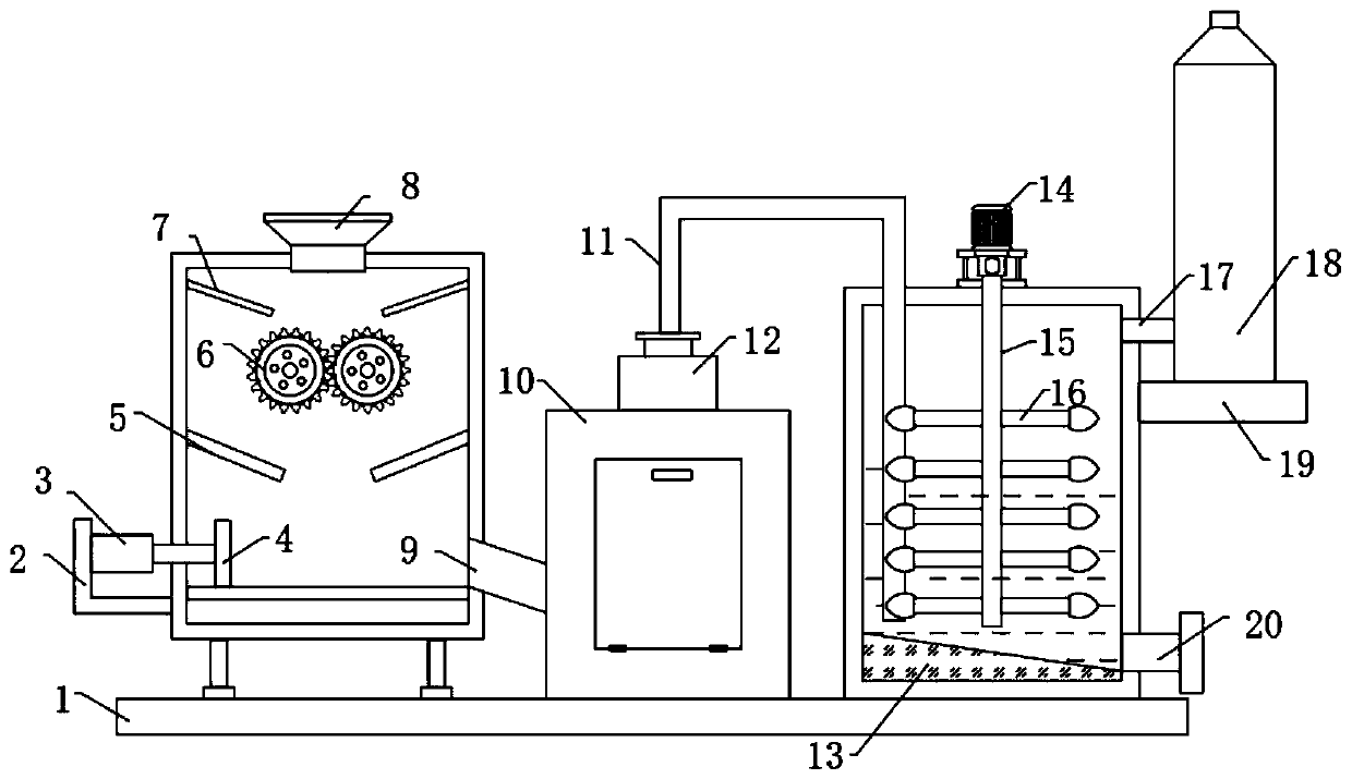
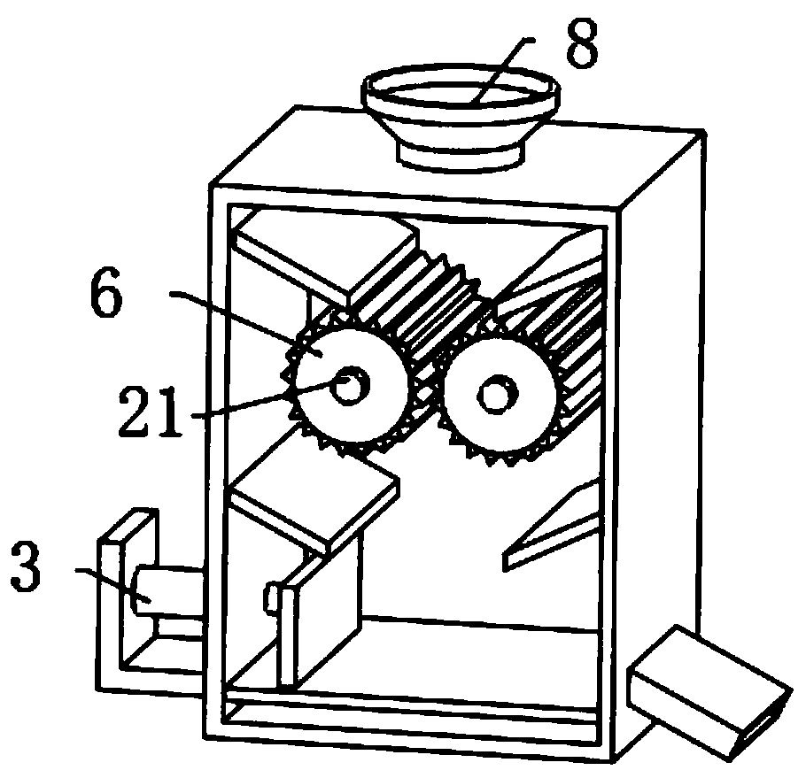
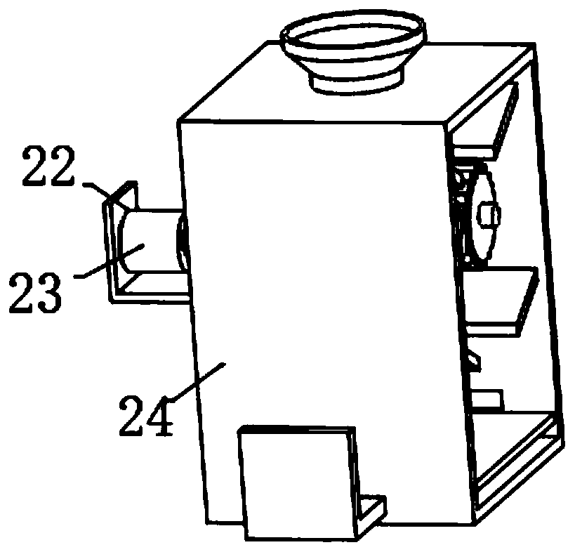
[0029] refer to Figure 1-4 , an industrial waste disposal device for environmental protection, comprising a bottom plate 1, a crushing box 24, an incinerator 10 and a mixing box are fixed on the top outer wall of the bottom plate 1 by screws, and a second connecting plate is fixed on one side of the crushing box 24 by screws 22. The outer wall of one side of the second connecting plate 22 is fixed with a second motor 23 by screws, and the inner wall of the crushing box 24 is connected with two second rotating rods 21 through bearings, and the output shaft of the second motor 23 is connected by a coupling On the outer wall of one of the second rotating rods 21, the outer wall of one side of the crushing box 24 is fixed with a pusher mechanism by screws, and the first inclined plate 5 and the second inclined plate 7 are welded on both sides of the inner wall of the crushing box 24, and the mixing box The top outer wall of the mixing box is fixed with a stirring mechanism by scr...

Embodiment 2

[0033] refer to Figure 5 , an industrial waste treatment device for environmental protection, including, and also including an exhaust fan 27 fixed to the outer wall of the incinerator 10 by screws, the output end of the exhaust fan 27 and the top inner wall of the incinerator 10 are connected by a flange with the same first Two conduits 28 .

[0034] Connect the equipment to the power supply, connect the hydraulic rod 3 to the hydraulic system, put industrial waste from the feed port 8 into the crushing box 24, turn on the second motor 23, and the second motor 23 drives the second rotary rod 21 to rotate and then crush The roller 6 crushes the industrial waste, adjusts the length of the hydraulic rod 3, so that the push plate 4 pushes the crushed waste to the chute 9, and the waste enters the incinerator 10 for incineration, and the waste gas generated by the incineration passes through the purifier 12 and the air duct 11 Enter the mixing box, turn on the first motor 14, th...


PUM


Abstract

The invention belongs to the technical field of waste treatment, and particularly relates to an industrial waste treatment device for environmental protection. In view of the problem of incomplete incineration, the following scheme is proposed: the industrial waste treatment device comprises a bottom plate, the outer wall of the top of the bottom plate is provided with a crushing box, an incinerator and a mixing box, the outer wall of one side of the crushing box is provided with a second connecting plate, the outer wall of one side of the second connecting plate is provided with a second motor, the inner wall of the crushing box is connected with two second rotating rods through bearings, and an output shaft of the second motor is connected to the outer wall of one of the second rotatingrods through a coupling, the outer wall of one side of the crushing box is provided with a pushing mechanism, two sides of the inner wall of the crushing box are respectively provided with a first inclined plate and a second inclined plate, and the outer wall of the top of the mixing box is provided with a stirring mechanism. The industrial waste treatment device is provided with the second motor,the second rotating rods and a crushing roller, the second motor drives the second rotating rods to rotate, then the crushing roller conducts crushing treatment on the waste, and waste incineration can be more thorough.

Description

technical field [0001] The invention relates to the technical field of garbage treatment, in particular to an industrial garbage treatment device for environmental protection. Background technique [0002] Industrial waste refers to the solid waste discharged during the production process of machinery, light industry and other industries. Such as mechanical industry cutting debris, grinding debris, waste sand, etc., activated carbon slag in the food industry, bricks, tiles, gravel, concrete fragments, etc. in the silicate industry and construction industry. [0003] After retrieval, the Chinese patent authorization number is CN108800151B, which discloses a green and environmentally friendly industrial waste incinerator, including a furnace body, a tail gas treatment device and a PLC control system. The tail gas treatment device includes a first tail gas treatment device and a second tail gas treatment device. device; the top of the furnace body is provided with a garbage fe...

Claims


Application Information

Patent Timeline
Patent Type & Authority Applications(China)
IPC IPC(8): F23G5/033F23G5/44F23J15/04F23L7/00
CPCF23G5/033F23G5/444F23G2201/80F23J15/04F23J2217/50F23L7/007Y02E20/34
Inventor 农彩丽
Owner 吕玲
Learn More