
Semiconductor structure and preparation method thereof

A semiconductor and isolation structure technology, which is applied in the field of semiconductor structure and its preparation, can solve the problems of difficult production, device size reduction, large parasitic resistance, etc., and achieve the effect of reducing the difficulty of forming, reducing the parasitic resistance, and reducing the parasitic resistance

Pending Publication Date: 2020-03-31
CHANGXIN MEMORY TECH INC
View PDF0 Cites 2 Cited by
  • Summary
  • Abstract
  • Description
  • Claims
  • Application Information

AI Technical Summary

Problems solved by technology

[0003] However, as the size of semiconductor devices continues to shrink, curved bit lines require complex optical proximity effect correction during exposure and development, making it very difficult to manufacture
In addition, there is a relatively large parasitic resistance in the wire of the curved or wavy bit line, which is not conducive to the reduction of the device size

Method used


Image

  • Semiconductor structure and preparation method thereof
  • Semiconductor structure and preparation method thereof
  • Semiconductor structure and preparation method thereof

Examples


Embodiment 1

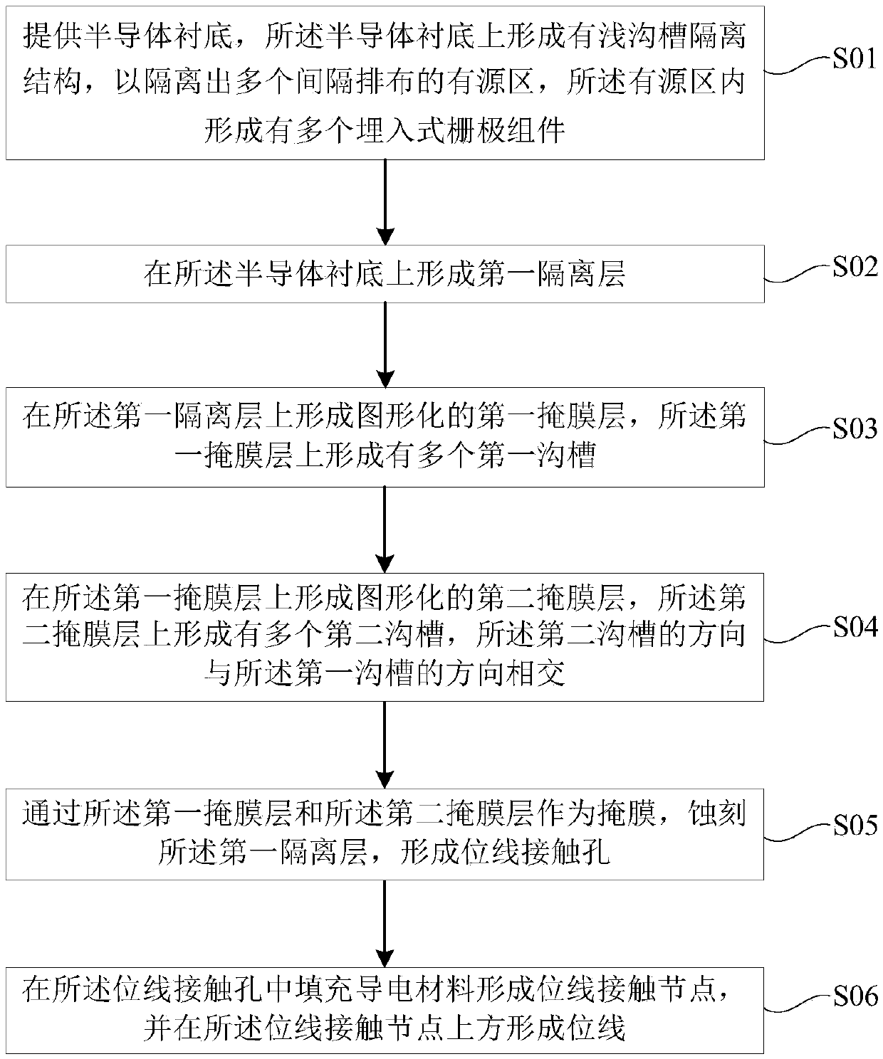
[0099] This embodiment provides a semiconductor structure preparation method, such as figure 2 As shown, the semiconductor structure preparation method at least includes the following steps:

[0100] S01, providing a semiconductor substrate, forming a shallow trench isolation structure on the semiconductor substrate to isolate a plurality of active regions arranged at intervals, and forming a plurality of buried gate components on the active region ;

[0101] S02, forming a first isolation layer on the substrate;

[0102] S03, forming a patterned first mask layer on the first isolation layer, where a plurality of first grooves are formed on the first mask layer;

[0103] S04, forming a patterned second mask layer on the first mask layer, forming a plurality of second grooves on the second mask layer, the direction of the second grooves is the same as that of the first mask layer The directions of the grooves intersect;

[0104] S05. Using the first mask layer and the seco...

Embodiment 2

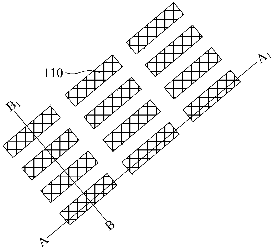
[0122] Continue to refer to the attached Figures 3 to 14-2B , the present invention also provides a semiconductor structure, in this embodiment, the semiconductor structure at least includes:

[0123] A semiconductor substrate 100, the semiconductor substrate 100 has a shallow trench isolation structure 125 to isolate a plurality of active regions 110 arranged at intervals, and the active region 110 has a plurality of buried gate components 215 ;

[0124] The first isolation layer 220, such as Figure 4-2 As shown in A, the first isolation layer 220 is located above the semiconductor substrate 100 .

[0125] The bit line contact node 375, the bit line contact node 375 is located at least part of the active region and part of the shallow trench isolation structure 125 between the adjacent buried gate components 215 in the same active region 110 , the bit line contact node 375 is isolated by the first isolation layer 220; as Figure 11B As shown, in a preferred embodiment o...


PUM


Abstract

The invention provides a semiconductor structure and a preparation method thereof, and the method at least comprises the steps: forming a plurality of active regions which are arranged at intervals ona semiconductor substrate, and forming a plurality of embedded gate assemblies in the active regions; forming a first isolation layer on the substrate; etching the first isolation layer to form a bitline contact hole; filling the line contact hole with a conductive material to form a bit line contact node having a first width, with a linear bit line having a second width less than the first width is formed over the bit line contact node. The bit line contact hole covers at least part of the active regions and part of the shallow trench isolation structure between the adjacent gate assembliesin the same active regions. The formed bit line is in good contact with a bit line contact node and well avoids a capacitor contact region. The optical proximity effect correction difficulty in the bit line forming process is reduced, the forming difficulty is reduced, and meanwhile the parasitic resistance in the bit line is effectively reduced. Reduction of the size of a memory is facilitated,and good functionality of the memory is ensured.

Description

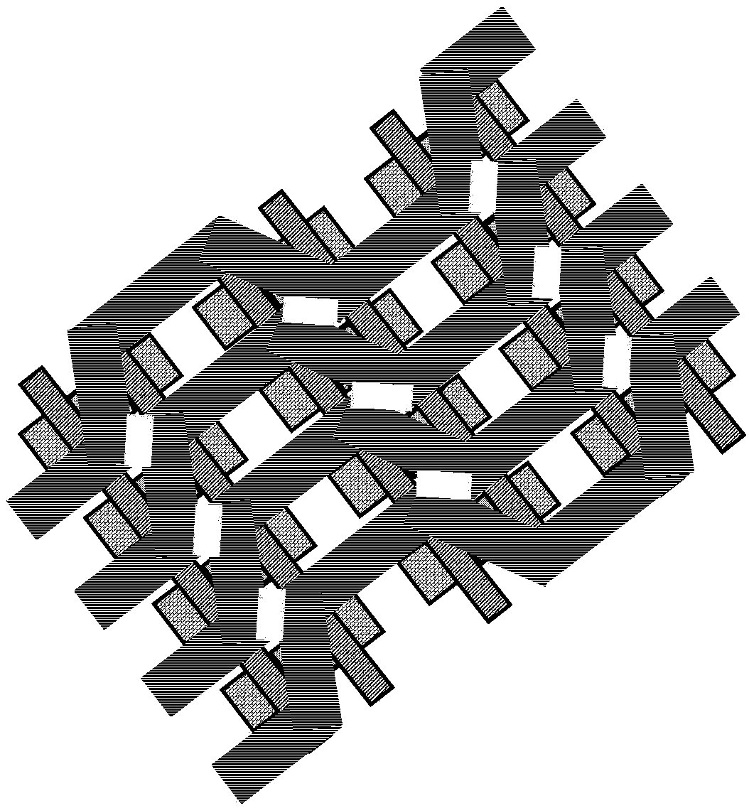
technical field [0001] The invention relates to the technical field of semiconductor integrated circuit manufacturing, in particular to a semiconductor structure and a preparation method thereof. Background technique [0002] A dynamic random access memory (DRAM) cell includes a capacitor and an access transistor for storing charge. Usually, in order to bypass the capacitor contact node, the bit line is often formed into a curved or wavy structure, such as figure 1 The curved structure shown. [0003] However, as the size of semiconductor devices continues to shrink, the curved bit lines require complex optical proximity effect correction during exposure and development, making it very difficult to manufacture. In addition, there is a relatively large parasitic resistance in the wire of the bent or wavy bit line, which is not conducive to reducing the size of the device. Contents of the invention [0004] In view of this, the present invention provides a semiconductor s...

Claims


Application Information

Patent Timeline
Patent Type & Authority Applications(China)
IPC IPC(8): H01L21/8242H01L27/108H10B12/00
CPCH10B12/30H10B12/02
Inventor 不公告发明人
Owner CHANGXIN MEMORY TECH INC
Learn More