Permanent magnet brake for adjusting magnetic field intensity

A technology of magnetic field strength and permanent magnets, applied in the direction of permanent magnet clutches/brakes, electrical components, electromechanical devices, etc., can solve the problems of damage to the car's own parts, reduce the service life of parts, and the speed difference between the inner and outer rings cannot be balanced. The effect of reducing vibration, reducing vibration and noise

Inactive Publication Date: 2020-03-31
郝心怡
View PDF0 Cites 2 Cited by
  • Summary
  • Abstract
  • Description
  • Claims
  • Application Information

AI Technical Summary

Problems solved by technology

The brake device of the prior art uses mechanical transmission to brake, and when there are too many emergency brakes, it will cause damage to the parts of the car itself and reduce the service life of the parts
At the same time, the permanent magnet brake of the prior art is not provided with a magnetic isolation component, and there is no electronic control system to control the magnetic isolation component and the spline to make it work together. causing ineffective wear

Method used


Image

  • Permanent magnet brake for adjusting magnetic field intensity
  • Permanent magnet brake for adjusting magnetic field intensity
  • Permanent magnet brake for adjusting magnetic field intensity

Examples


Embodiment Construction

[0020] Further illustrate the present invention in conjunction with accompanying drawing.

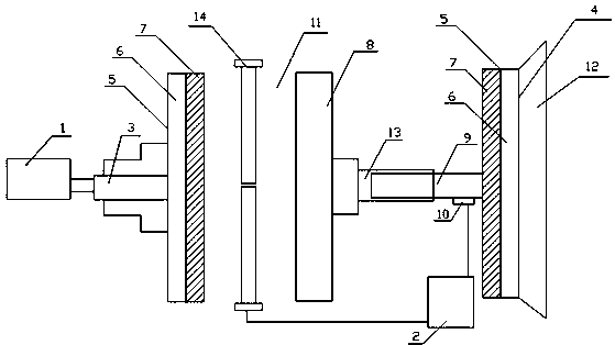
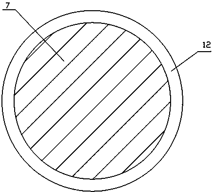
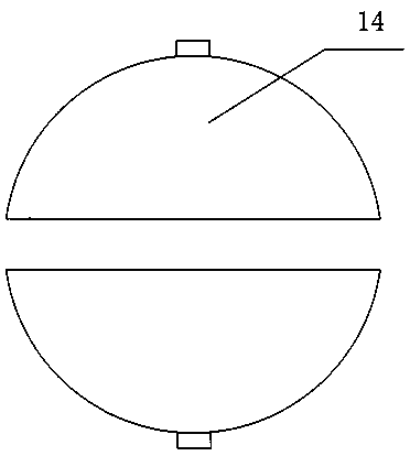
[0021] like figure 1 and figure 2 , the motor 1 is connected with the motor shaft 3, the motor shaft 3 is connected with the conductor rotor 5, the conductor rotor 5 is composed of an outer steel body 6 and an inner copper conductor 7; a permanent magnet 8 is arranged opposite to the conductor rotor 5, and the permanent magnet 8 is connected with the drive shaft 9 is connected through the coaxial sleeve 13, and the drive shaft 9 is connected with the load 4. The load 4 is composed of another set of conductor rotor 5 and hub 12; an air gap 11 is formed between the conductor rotor 5 and the permanent magnet 8; the spline 10 is connected with the drive shaft 9; one end of the coaxial sleeve 13 is connected with the permanent magnet 8, and the other One end is connected with the drive shaft 9; the electronic control system 2 is connected with the magnetic isolation component 14 and the s...


PUM


Abstract

The invention provides a permanent magnet brake capable of adjusting magnetic field intensity. The permanent magnet brake mainly comprises an engine, a motor shaft, a conductor rotor, a steel body, acopper conductor, a permanent magnet, a spline, a load, a coaxial sleeve, a magnetic isolation assembly and the like. The conventional mechanical connection transmission between a motor and a load isreplaced by an air gap torque transmission mode, and the magnetic isolation assembly and the spline are controlled by an electronic control system, so that the brake effect is improved. The motor is not mechanically connected with a load, has a load protection function, and can reduce vibration and noise at the same time. The coaxial sleeve can balance the rotating speed difference of the inner ring and the outer ring, so that a vehicle is more stable. The device is of a pure mechanical structure, does not consume electricity, does not generate harmonic waves, electromagnetic interference andother pollution, and is a green and environment-friendly product. Buffer starting and multiple times of starting can be achieved. A conductor rotor is installed on the load.

Description

technical field [0001] The invention relates to a brake device, in particular to a permanent magnet brake for adjusting the strength of a magnetic field. Background technique [0002] The braking device of the prior art is to rely on the principle of lever and gear to realize the mechanical connection mode of automobile drive. This method has the disadvantages of high energy consumption of the motor and obvious system vibration. [0003] It is still a new topic to apply permanent magnet drive technology to the automotive field. Permanent magnet magnetic drive technology is a new technology that uses the magnetic force of permanent magnet materials to realize the non-contact transmission of force and torque based on the basic theory of modern magnetism. The devices that implement this technology are called permanent magnet drives. [0004] In 1940, the British used magnetic drive pumps for the first time to solve the leakage problem of chemical pumps with dangerous media. ...

Claims


Application Information

Patent Timeline
Patent Type & Authority Applications(China)
IPC IPC(8): H02K49/10
CPCH02K49/108
Inventor 郝心怡
Owner 郝心怡
Why Eureka
Try Eureka