
Bus and inverter circuit combined modulation controller and strategy suitable for small-inductance motor

A technology of inverter circuit and joint modulation, which is applied in the field of bus and inverter circuit joint modulation controllers and strategies, can solve problems such as increased cost of the controller, failure to work, poor system stability, etc., to reduce harmonic content, suppress Torque and current fluctuations, effects of increasing switching frequency and modulation

Active Publication Date: 2020-03-31
TIANJIN UNIV
View PDF3 Cites 0 Cited by
  • Summary
  • Abstract
  • Description
  • Claims
  • Application Information

AI Technical Summary

Problems solved by technology

[0003] The coreless structure of this type of motor makes the stator winding inductance very small, while the traditional controller is based on a voltage source inverter, and the switching frequency generally does not exceed 20kHz. It is used to drive such a small inductance motor, and the motor winding current fluctuates greatly. , and even intermittent and overcurrent phenomena may occur, the volt-second balance may not be satisfied within one control cycle, and the vector synthesis conditions may not be satisfied, resulting in poor stability of the entire system, or even failure to work
Therefore, the application of such motors in the drive field is limited
[0004] Since the main cost of the controller comes from power devices such as IGBTs in the inverter circuit, replacing all power devices with new IGBT devices with superior performance to increase the switching frequency of the system can reduce the current fluctuation of this type of motor, but the controller The cost is greatly increased, and higher requirements are placed on the electromagnetic compatibility of the system

Method used


Image

  • Bus and inverter circuit combined modulation controller and strategy suitable for small-inductance motor
  • Bus and inverter circuit combined modulation controller and strategy suitable for small-inductance motor
  • Bus and inverter circuit combined modulation controller and strategy suitable for small-inductance motor

Examples


Embodiment Construction

[0024] The present invention will be further described below in conjunction with the accompanying drawings.

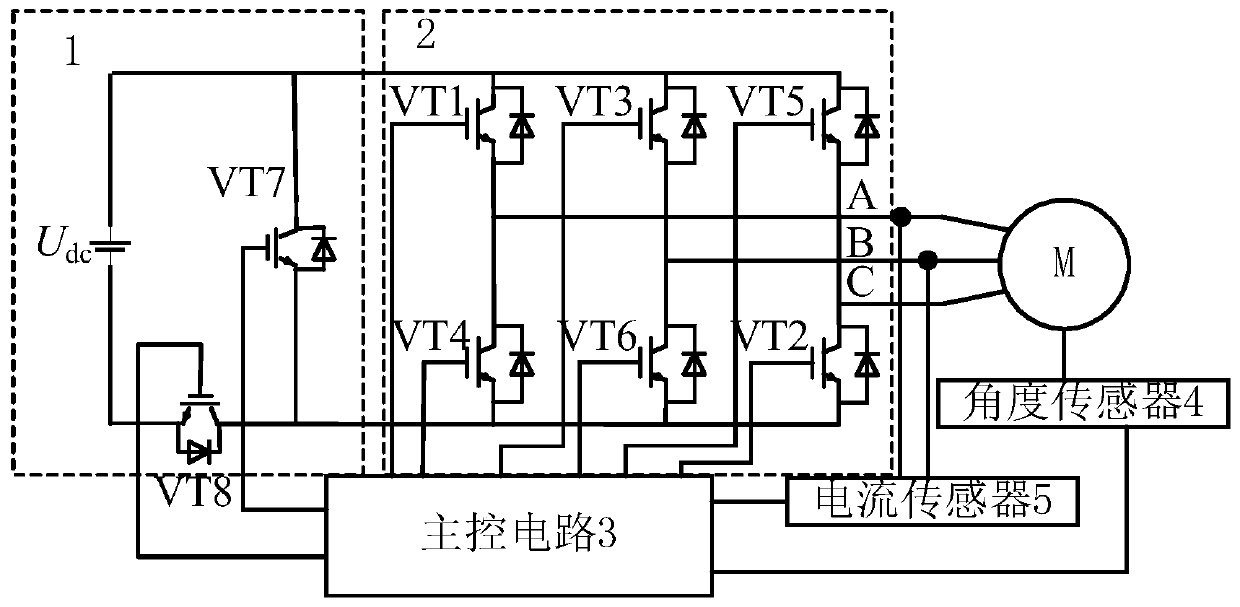
[0025] Such as figure 1 As shown, the present invention is applicable to the combined modulation controller of the bus bar and the inverter circuit of the small inductance motor, which is divided into two parts: the power circuit and the control circuit. The power circuit is composed of a modulating bus bar circuit 1 and a three-phase inverter circuit 2. The control circuit is composed of a main control circuit 3 , an angle sensor 4 and a current sensor 5 . The control signal input end of the modulating bus circuit 1 is connected to the signal output end of the main control circuit 3 . The control signal input end of the three-phase inverter circuit 2 is connected to the signal output end of the main control circuit 3 . The output shaft of the small inductance motor M is connected to the signal input terminal of the main control circuit 3 through the angle sensor 4, ...


PUM


Abstract

The invention discloses a bus and inverter circuit combined modulation controller suitable for a small-inductance motor. The bus and inverter circuit combined modulation controller comprises a modulatable bus circuit, a three-phase inverter circuit, a main control circuit, an angle sensor and a current sensor, the modulatable bus circuit comprises a direct-current power supply, a seventh power switching device and an eighth power switching device; the three-phase inverter circuit comprises a first power switching device, a second power switching device, a third power switching device, a fourthpower switching device, a fifth power switching device and a sixth power switching device. A modulation strategy: giving parameters delta and h; solving Vi, Vm, Ti and Tm; calculating a coefficient k= (Ti + Tm) / [(1-delta) Ts]; solving the action time of the zero bus voltage vector as [(k-1) (Ti + Tm)] / (1-delta), and calculating the duty ratio of VT7 as [(k-1) (Ti + Tm)] / [(1-delta) h]; and the VT7 outputs according to the duty ratio. According to the invention, the current and torque ripples in the control drive of the small-inductance motor are reduced.

Description

technical field [0001] The invention relates to the field of motor drive, and more specifically relates to a bus bar and inverter circuit joint modulation controller and strategy suitable for small inductance motors. Background technique [0002] The small-inductance motor represented by the disc-type coreless permanent magnet synchronous motor has many advantages such as large overload capacity, fast response speed, high back EMF sine degree, and high linearity of motor parameters. This type of motor can be used in a variety of demanding applications, such as motors for electric vehicle hubs, robotic arm drive motors, etc. [0003] The coreless structure of this type of motor makes the inductance of the stator winding very small, while the traditional controller is based on a voltage source inverter, and the switching frequency generally does not exceed 20kHz. It is used to drive such a small inductance motor, and the current of the motor winding fluctuates greatly. , and ...

Claims


Application Information

Patent Timeline
Patent Type & Authority Applications(China)
IPC IPC(8): H02P21/05H02P6/10H02P27/12
CPCH02P21/05H02P6/10H02P27/12H02P2207/05
Inventor 王晓远李小宁
Owner TIANJIN UNIV
Learn More