Pulse width and duty ratio modulation signal generation circuit and method
A technology of duty cycle modulation and modulation circuit, which is applied in the electronic field and can solve problems such as poor linearity, complex system, and high cost
- Summary
- Abstract
- Description
- Claims
- Application Information
AI Technical Summary
Problems solved by technology
Method used
Image


Examples
Embodiment Construction
[0030] Refer below Figure 1-Figure 3 The specific implementation of the pulse width and duty ratio modulation signal generating circuit and method of the present invention will be described in detail.
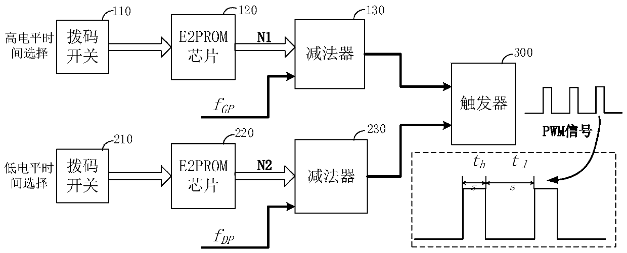
[0031] Such as figure 1 As shown, the pulse width and duty ratio modulation signal generation circuit provided by the present invention includes a flip-flop 300 and a high-level modulation circuit and a low-level modulation circuit connected to the two input terminals of the flip-flop 300;
[0032] Described high-level modulation circuit comprises the dial switch 110, E2PROM chip 120 and subtractor 130 that are connected in sequence, and this dial switch 110 is used for selecting the counter value N1 stored in the E2PROM chip 120, and this E2PROM chip 120 will count value N1 N1 is sent to the subtractor 130 as the initial value to start counting, and the subtractor 130 is based on the initial value and the set counting frequency (clock frequency) f GP Count down, and the fli...
PUM
 Abstract
Description
Claims
Application Information
 - R&D
- Intellectual Property
- Life Sciences
- Materials
- Tech Scout
- Unparalleled Data Quality
- Higher Quality Content
- 60% Fewer Hallucinations
Browse by: Latest US Patents, China's latest patents, Technical Efficacy Thesaurus, Application Domain, Technology Topic, Popular Technical Reports.
© 2025 PatSnap. All rights reserved.Legal|Privacy policy|Modern Slavery Act Transparency Statement|Sitemap|About US| Contact US: help@patsnap.com