[0003] In view of this, the present invention provides a single-screen restoration display computer
system for a surround-view network camera (IPC) group to solve the problem of restoring the
azimuth topology of video images collected in a geographic three-dimensional space and looking around multi-directional scenes in the prior art. In order to solve the above-mentioned problems, the technical solution provided by the present invention is as follows. According to the
habit and
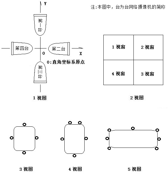
consensus of people looking around in the three-dimensional space around the scene with the front, back, left, and right directions, such as Figure 4 As shown in the view of 1, establish an
azimuth compass, on this basis, design a four-
azimuth compass including four azimuths evenly distributed (such as Figure 4 2 view of ), six-direction six-direction
compass (such as Figure 4 3), the four-direction compass includes front, right, rear, and left, and the six-direction compass includes left front, right front, right, right rear, left rear, and left , each azimuth has attributes including azimuth name,
horizontal angle of view, and
vertical angle of view, and adjacent azimuths have a fixed azimuth topological relationship. The multi-channel video computer
system topology diagram of a network camera group that looks around a multi-directional scene
video image in a geographical three-dimensional space is as follows Figure 5 As shown in the view of 1, there are two symmetrical network camera groups in a plane Cartesian coordinate system, such as Figure 22 As shown in the view of 1, four network camera groups are arranged evenly, such as Figure 5 As shown in the 2 view of , the group of six network cameras arranged evenly Figure 5 As shown in Figure 3, the types of multiple network camera groups include two network camera groups, four network camera groups, six network camera groups, and eight network camera groups. Each network camera in the network camera group has a Its own device ID, video
network address, and horizontal viewing angle (40 to 110 degrees) attribute, each network camera of the network camera group is 0 to 300 cm away from the origin of the plane Cartesian coordinate system, and is actually installed in a horizontally placed The distance difference between each network camera on the carrying device and the origin of the plane Cartesian coordinate system can be between 0 and 200 centimeters, and the difference between the longitudinal distances between the network cameras relative to the plane of the plane Cartesian coordinate system It can be between 0 and 50 centimeters, at the geometric center point of a horizontal section of a horizontally placed carrying device, with one direction as the reference, superimposing the six-direction compass, according to the
rectangular coordinates of the plane where the six network camera groups are located The system is superimposed with the six-direction compass, and the six network camera groups are installed to form a six-eye
compound eye network camera, such as Figure 7 As shown, the four-eye compound-eye network camera is a special case of the six-eye compound-eye network camera, such as Figure 6 As shown, the left and right binocular network cameras are a special case of the four-eye compound eye network camera, as Figure 22 As shown in Figure 2, the types of multi-eye compound eye network cameras include left and right binocular network cameras, four-eye compound eye network cameras, and six-eye compound eye network cameras. The types of multi-eye compound eyes include left and right binocular, four-eye compound eyes, and six-eye compound eyes. Just like two-wheeled carts, four-wheeled cars, and six-wheeled trucks are different from a fleet composed of N unicycles, the traditional video surveillance system composed of N network cameras with left and right binocular, four-eye compound eyes, and six-eye compound eyes areas focuses on the problem. There are essential differences and significant progress in the use of technical means and the effect achieved. The left and right
binoculars include the left azimuth eye and the right azimuth eye, and the four-eye compound eyes include the front azimuth eye, right azimuth eye, rear azimuth eye, left azimuth eye, and left azimuth eye. Eyes, the six-eye compound eye includes a left front azimuth eye, a right front azimuth eye, a right azimuth eye, a right rear azimuth eye, a left rear azimuth eye, and a left azimuth eye. The camera, an azimuth eye window on the single screen, and the multi-eye compound eye constitute a schematic diagram as shown in Figure 8 As shown, the
data structure of the azimuth eye includes the spatial attributes of the image collection point of the
horizontal angle of view, the
vertical angle of view, and the
horizontal angle of view, and includes the video
network address, the azimuth eye window with the topological relationship of the
viewfinder orientation, the name identification of the
viewfinder orientation, and the color identification of the
viewfinder orientation The surround-view azimuth imaging display properties, based on the overlapping
field of view of both eyes is about 120 degrees, the best viewing angle is 90 degrees, the comfortable
field of view of one eye is about 60 degrees, and the golden ratio of the width and height of the
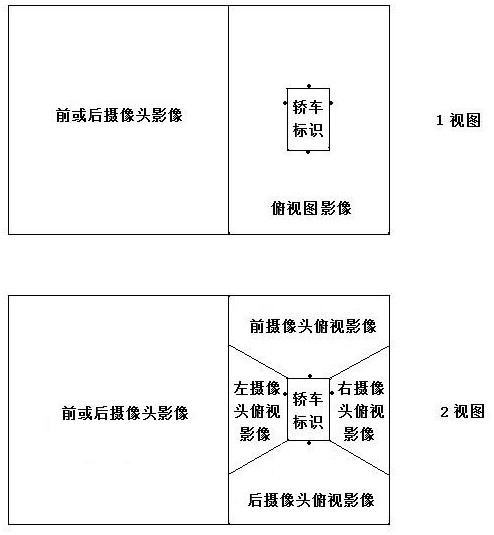
field of view of both eyes is 16:9. The spatial attribute of the image collection point of the vertical viewing angle and the horizontal viewing angle is to intercept and segment the multi-directional scene framing image of the same time and space collected by the multi-eye compound eye network camera in a rectangle, just like a uniformly arranged vertical and horizontal plane around an origin The image on the three-dimensional rectangular four-sided mirror or six-sided mirror is tiled on the horizontal plane in situ, and the image of the four-eye compound eye network camera is as follows: Figure 9 As shown in view 1 of , the image of the six-eye compound eye network camera is as follows Figure 10 As shown in view 1, the azimuth viewfinder and azimuth eye windows are set on the single screen, and the azimuth eye windows are assembled to form a ring-type
clockwise distribution window group that keeps the original image azimuth topological relationship unchanged, and a computer that visually restores the geographical three-dimensional space surround-view azimuth image on the same screen Visual compound eye
clockwise with the same shape and equal area
imaging algorithm. In the single screen, through the circular
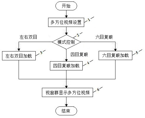
clockwise window group layout design, the image in the window will image the three-dimensional scene in a two-dimensional plane. On the single screen Composing a multi-eye compound eye window group with the space attribute of the azimuth eye image collection point and the look-around azimuth imaging display attribute, the types of the multi-eye compound eye window group include left and right binocular window groups, four-eye compound eye window groups, and six-eye compound eye window groups, The left and right double-window groups include a left azimuth eye window and a right azimuth eye window, and the four-eye compound eye window group includes a front azimuth eye window, a right azimuth eye window, a rear azimuth eye window, and a left azimuth eye window. The window group includes the left front azimuth eye window, the right front azimuth eye window, the right azimuth eye window, the right back azimuth eye window, the left back azimuth eye window, and the left azimuth eye window. Figure 21 As shown in the 2 views, the reference imaging of the four-eye compound eye network camera on the single screen is as follows Figure 9 As shown in the 2 view, the six-eye compound eye network camera base imaging six-eye compound eye window group on the single screen is as follows Figure 10 As shown in the 2 views, the multi-eye compound eye window group, for the left and right
binoculars, can specifically be left and right two-way two-way windows (such as Figure 21 shown), for the
quadrilateral compound eyes, its types include cross looking quadruple windows (such as Figure 11 as shown), horizontal screen front-view three windows (such as Figure 12 as shown), horizontal screen back view three windows (such as Figure 13 as shown), front and rear two-way dual windows (such as Figure 14 as shown), left and right two-way two windows (such as Figure 21 shown), for the six-eye compound eye, its types include six-direction viewing and six windows (such as Figure 15 as shown), horizontal screen front view four windows (such as Figure 16 as shown), Tianzi front view four windows (such as Figure 17 as shown), horizontal screen rear view four windows (such as Figure 18 as shown), Tianzi rear view four windows (such as Figure 19 as shown), the four front and rear windows of Tianzi (such as Figure 20 as shown), left and right two-way two windows (such as Figure 21 shown), the windows of the azimuth eyes have the same height, the
aspect ratio is between 8:3 and 4:3, the maximum width difference is less than the window height, the green, yellow and red of the integrated traffic lights, and the front and right sides of the car , Rear, and left lights have the same color, set the frame color of the front azimuth eye window to white or green, the color of the right azimuth eye window frame to yellow or orange, the color of the rear azimuth eye window frame to red, and the color of the left azimuth eye window frame to yellow or orange Using the various technical means of the azimuth compass, azimuth eye camera, azimuth
eye color labeling, azimuth eye name labeling, and azimuth eye window group layout, the images collected by the various azimuth eye cameras of the multi-eye compound eye network camera are restored to form a suitable Multi-eye compound eye window group
image display with different needs can achieve synchronous, same-screen, intuitive comparison, including front, rear, left, right, and left-right look-around-
geographic space, three-dimensional and multi-directional scene images of the same time and space. 2, 3, 4, 6) Luhuan's visual images form a clear image effect at a glance, based on a group of network cameras + single-screen window group, the name of the azimuth eye window is equivalent to the
eyebrow, and the frame of the azimuth eye window is equivalent In the eye frame, the
video screen displayed in the window of the azimuth eye is equivalent to the
retina on the back wall of the eyeball, and the azimuth eye camera is equipped to form the azimuth eye, realizing the goal of multi-eye compound eye imaging of
insect compound eyes
bionics, from the network terminal From the user's point of view, they have the right to choose independently and actively the scene images of different orientations in the video collection scene, and change the scene images of a specific perspective selected by the on-site cameraman to operate a single or multiple cameras, and push them to the The traditional mode of remote viewers achieves an immersive effect similar to that of panoramic video technology, and realizes the effect of clear multi-directional images of the surrounding scenery that cannot be achieved by single-window display of panoramic video technology.


