
Mixing station and grout preparation method thereof

A mixing station and mixing device technology, which is applied in mixing plants, cement mixing devices, chemical instruments and methods, etc., can solve the problems that are easy to affect the slurry, and achieve the effect of avoiding uneven dryness and wetness, and avoiding damage

Inactive Publication Date: 2020-04-03
MAANSHAN HONGTAI BUILDING MATERIALS
View PDF9 Cites 5 Cited by
  • Summary
  • Abstract
  • Description
  • Claims
  • Application Information

AI Technical Summary

Problems solved by technology

[0006] Aiming at the problem in the prior art that the humidity of the aggregate easily affects the quality of the slurry product when the mixing station produces slurry, the present invention provides a mixing station and a slurry making method thereof, in which a humidity sensor is installed in the mixing device to obtain concrete material Slurry humidity, to determine the water demand for pulping, to achieve precise control of the amount of water added during the pulping process, so as to avoid affecting the quality of slurry products due to different aggregate humidity, and to produce high-quality concrete and other slurry

Method used


Image

  • Mixing station and grout preparation method thereof
  • Mixing station and grout preparation method thereof
  • Mixing station and grout preparation method thereof

Examples


Embodiment 1

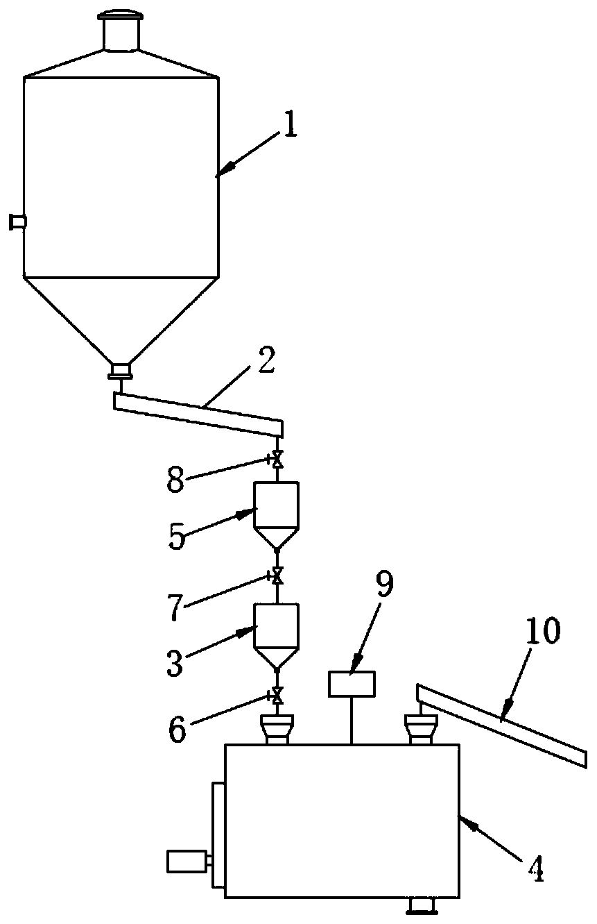
[0049] Such as figure 1 As shown in , a mixing station in this embodiment includes a mixing device 4 for mixing and preparing concrete slurry; and an aggregate supply system 10, which quantitatively supplies aggregates to the mixing device 4; and powder A supply system, which quantitatively supplies powder into the stirring device 4; and a water supply system 9, which quantitatively supplies water to the stirring device 4; the stirring device 4 is provided with a humidity sensor 44 for detecting the humidity of the aggregate, It is used to detect the humidity of the aggregate put into the stirring device 4.

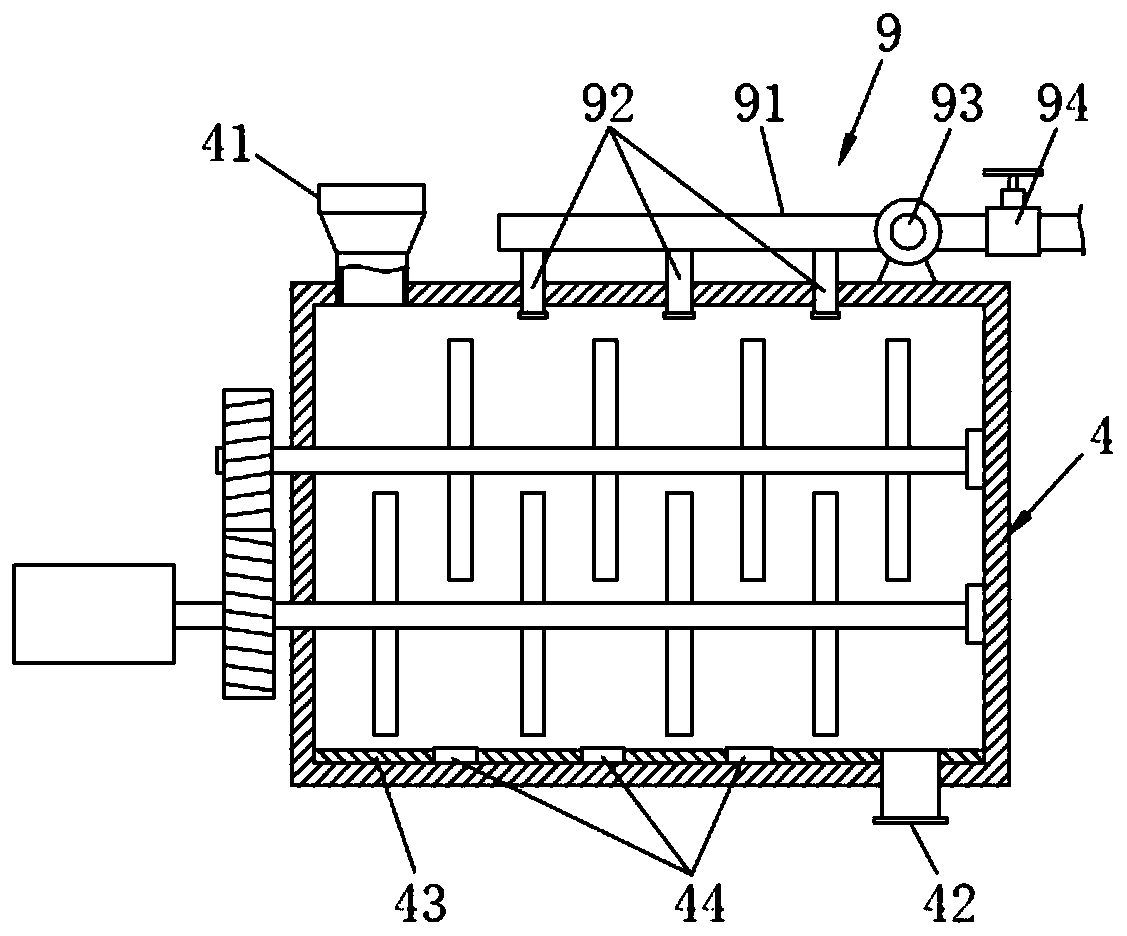
[0050] Such as figure 2 As shown in , the stirring device 4 in this embodiment includes a feeding port 41 and a slurry outlet 42, and the feeding port 41 is provided with a plurality of them, which are respectively used to put aggregate and powder into the stirring device 4; The feeding port 41 for feeding aggregates is set in cooperation with the aggregate supply syst...

Embodiment 2

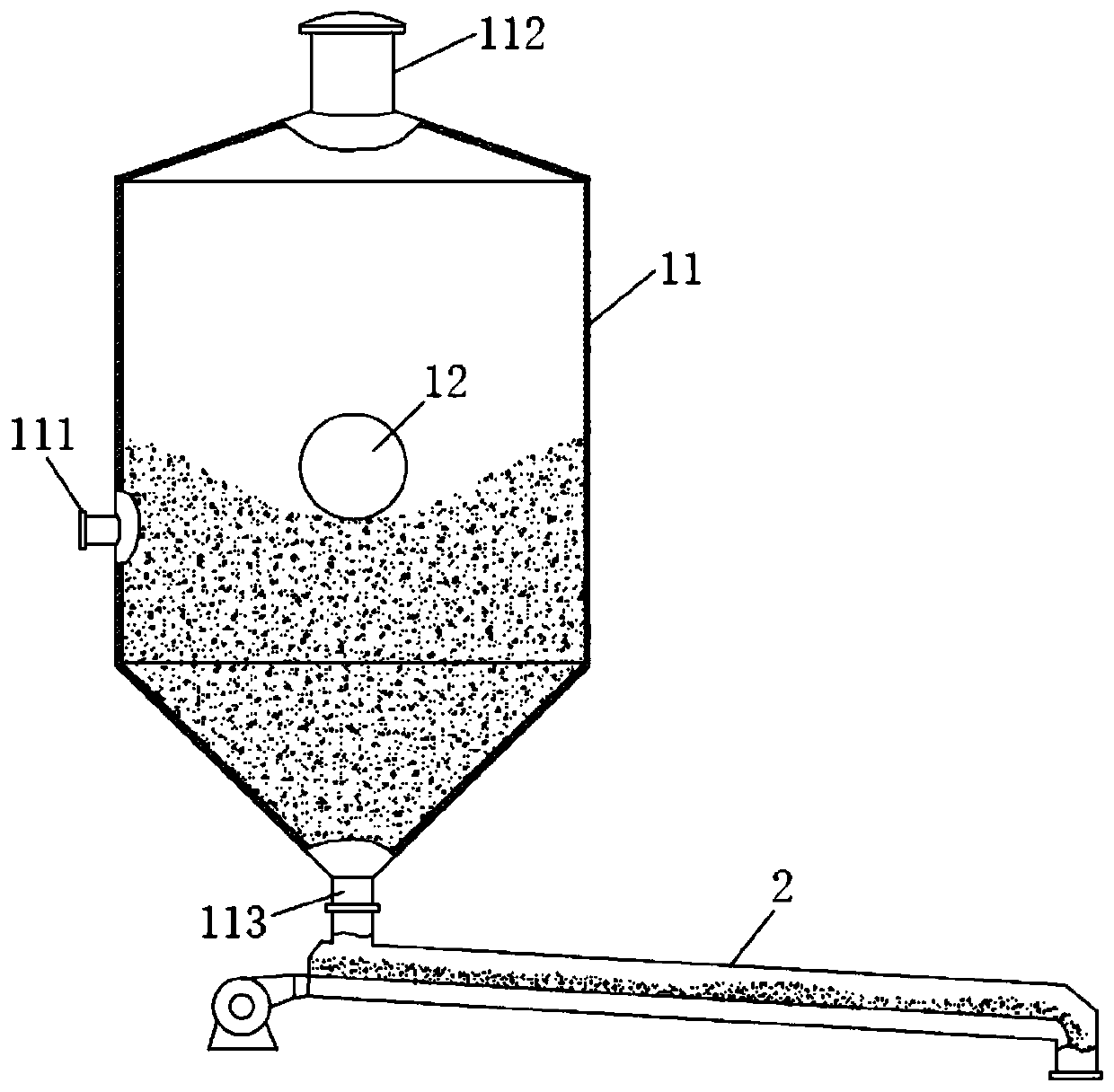
[0055] The stirring station in the present embodiment, basic structure is the same as in embodiment 1, difference and improvement are, as figure 1 As shown in , the powder supply system includes a powder tank 1, an air conveying chute 2, a metering bin 3 and a stirring device 4 connected in sequence, and the metering bin 3 is arranged on the stirring device 4 for feeding On the feeding port 41 of the powder, a buffer tank 5 is also arranged between the air conveying chute 2 and the metering bin 3 to store the powder conveyed by the air conveying chute 2 to avoid air conveying slant The tank 2 conveys more powder to the metering bin 3, so as to realize the precise and quantitative conveying of the powder. A butterfly valve I6 is arranged between the metering bin 3 and the stirring device 4, which is used to block the powder passage between the metering bin 3 and the stirring device 4 during the process of metering the amount of powder, so as to prevent the powder from directly ...

Embodiment 3

[0067] The mixing station in the present embodiment, basic structure simultaneously embodiment 2, difference and improvement are, as Figure 5 As shown in , the buffer tank 5 includes a buffer tank body 51 and a level gauge 52 , and the level gauge 52 is vertically inserted into the buffer tank body 51 .

[0068] After each quantitative delivery of powder, excess powder will enter the buffer tank 5. After long-term use, the amount of powder in the buffer tank 5 will accumulate until the buffer tank 5 is filled. If the staff cannot find out in time, it will affect the normal operation of the system.

[0069] Therefore, in this embodiment, the amount of powder inside is monitored by setting a level gauge 52 in the buffer tank 5. The remaining amount of powder exceeds 60% of the capacity of the level gauge 52. When conveying the powder, the butterfly valve II7 is opened after closing the closed butterfly valve I6, so that the powder in the buffer tank 5 is discharged into the me...


PUM


Abstract

The invention discloses a mixing station and a grout preparation method thereof, and belongs to the technical field of mixing stations. The mixing station comprises a mixing device, a powder supply system, an aggregate supply system and a water supply system. An inner lining board is arranged on the inner wall of the mixing device. Humidity sensors are arranged on the inner lining board. The watersupply system comprises a water supply main pipe and multiple water supply branch pipes. A flow meter and a valve are arranged on the water supply main pipe. The powder supply system comprises a powder tank, an air conveying inclined tank, a buffer tank and a metering bin which are sequentially arranged in a communicating manner. The metering bin is arranged on a feeding port of the mixing device. A butterfly valve I is arranged between the metering bin and the mixing device. A butterfly valve II is arranged between the buffer tank and the metering bin. A butterfly valve III is arranged between the air conveying inclined tank and the buffer tank. According to the mixing station and the grout preparation method, precise quantitative control can be conducted on powder added in the grout preparation process through the powder supply system, the water supply amount is determined according to the concrete grout humidity fed back by the humidity sensors, and therefore high-quality concretegrout with the precise material ratio can be prepared.

Description

technical field [0001] The invention relates to the technical field of mixing stations, in particular to a mixing station and a pulping method thereof. Background technique [0002] Mixing plant is also called concrete mixing plant, its main purpose is to mix concrete, which is often used in concrete engineering. The mixing station has high intelligent automation functions, and has the characteristics of compact structure, flexible layout, low investment, convenient disassembly and transportation, etc. It can realize various combinations and feeding methods according to user needs, and can produce dry hard and semi-dry hard , plasticity and various proportions of concrete, and realize the stone-wrapped mixing process, which greatly improves the quality of concrete. It is an ideal equipment for small and medium-sized building construction, highway and bridge construction, and commercial concrete, pipe piles, and cement prefabrication plants. [0003] The way to prepare concr...

Claims


Application Information

Patent Timeline
Patent Type & Authority Applications(China)
IPC IPC(8): B28C5/14B28C5/08B28C7/00B28C7/02B28C7/04B28C7/12
CPCB28C5/0806B28C5/147B28C5/148B28C7/0053B28C7/0076B28C7/024B28C7/044B28C7/0481B28C7/126
Inventor 梁梦琦梁俊曾少雷
Owner MAANSHAN HONGTAI BUILDING MATERIALS
Learn More