
Seamless steel tube evaporator

A technology of seamless steel pipe and evaporator, which is applied in the direction of evaporator/condenser, heat exchanger sealing device, application, etc., can solve the problems of long production cycle, inconvenient installation and operation, and easy water leakage, and reduce manufacturing and processing costs Processing, refrigeration sealing effect is good, the effect of high electric output efficiency

Pending Publication Date: 2020-04-03
深圳市家惠宝智能家居有限公司
View PDF0 Cites 0 Cited by
  • Summary
  • Abstract
  • Description
  • Claims
  • Application Information

AI Technical Summary

Problems solved by technology

[0002] At present, the structure of the evaporator in the ice machine is unreasonable, and it is all die-casting. Manufacturing requires die-casting to open the mold. The position and size of the evaporator are inconvenient to adjust. The thickness of the die-casting part is large. At the same time, the cooling copper tube needs to be cooled and evaporated by the refrigerant. The ice water in the main pipe of the ice machine leads to poor cooling effect of the ice machine, and the sealing effect of the main pipe of the evaporator is not good, and it is easy to leak water, and the manufacturing cost is high and the production cycle is long
[0003] At present, because the evaporator and the former are fixedly connected by flanges, it is inconvenient to install and disassemble. The structure of the main pipe of the evaporator and the cooling copper pipe is unreasonable. The connection structure between the ice cutter and the ice cutter is unreasonable, and the ice-making effect is not good, and the evaporator and the former are made of die-casting material, not food-grade stainless steel, so the ice-making is not environmentally friendly, which is not conducive to people's food health, and the manufacturing cost is high

Method used


Image

  • Seamless steel tube evaporator
  • Seamless steel tube evaporator
  • Seamless steel tube evaporator

Examples


Embodiment Construction

[0032] In order to fully understand the technical content of the present invention, the technical solutions of the present invention will be further introduced and illustrated below in conjunction with specific examples, but not limited thereto.

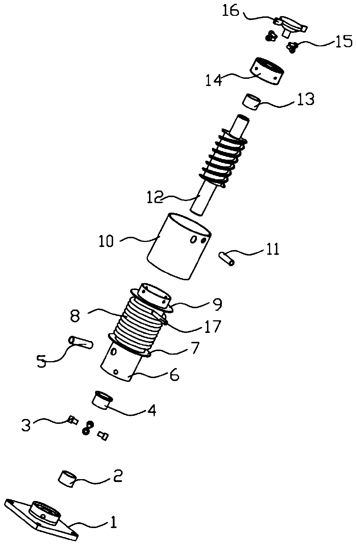
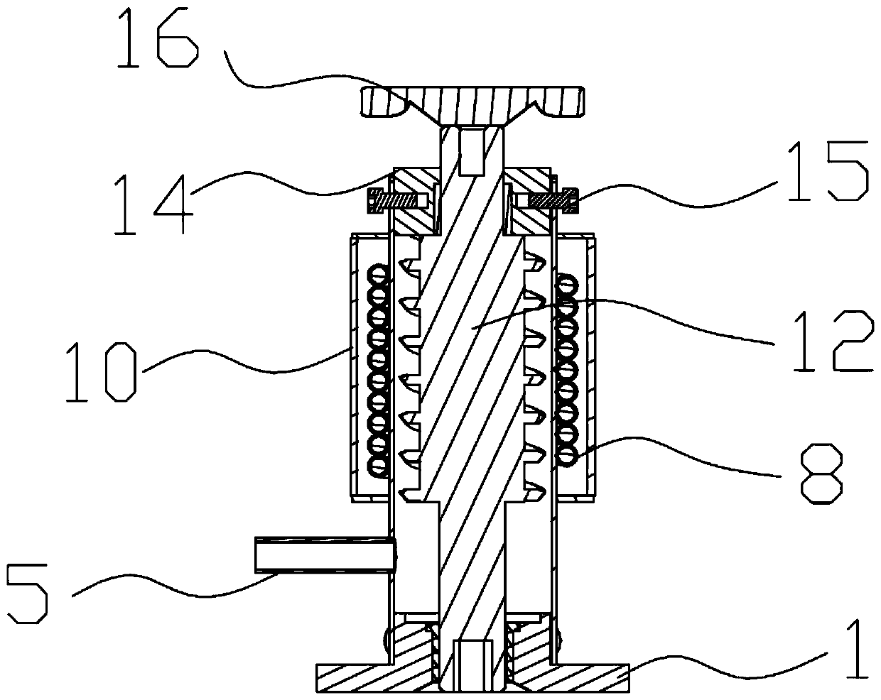
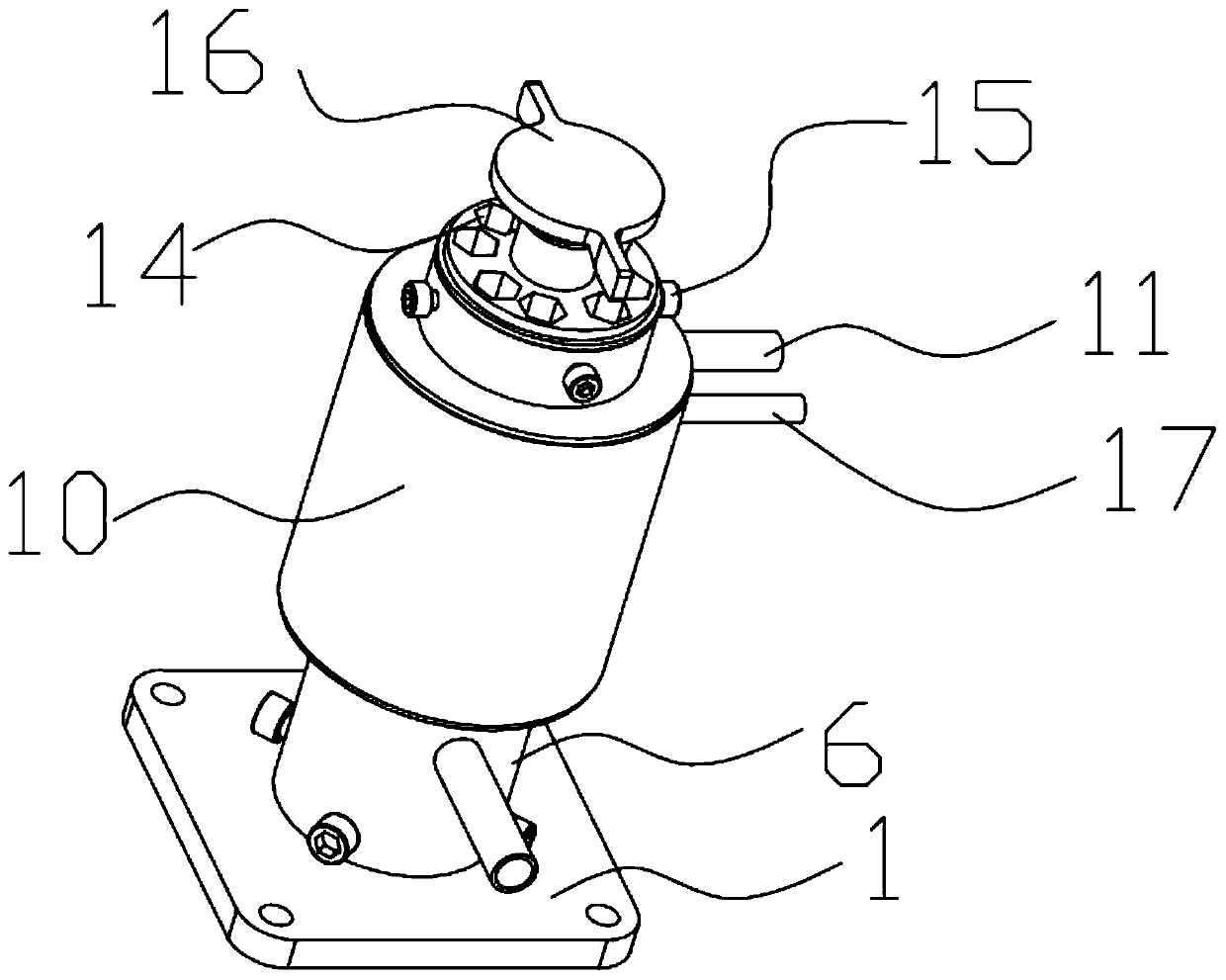
[0033] see Figure 1 to Figure 3 As shown, a seamless steel pipe evaporator includes an evaporator, an evaporator main tube 6 and a cooling copper tube. The evaporator main tube 6 and the cooling copper tube 8 are installed in the evaporator, and the outer circumference of the evaporator main tube 6 is closely surrounding A cooling copper tube 8 is provided, and the outside of the cooling copper tube 8 is fixedly connected to the evaporation outer sealing tube 10. The evaporator main tube 6 is a seamless steel tube, and one end of the evaporator main tube 6 is fixedly connected to the ice particle former 14. An ice blade 12 is arranged, and one end of the ice blade 12 is connected with a rotating motor, and the other end is fixedly c...


PUM

PropertyMeasurementUnit
Diameteraaaaaaaaaa
Thicknessaaaaaaaaaa

Abstract

The invention provides a seamless steel tube evaporator. The seamless steel tube evaporator comprises an evaporator and a refrigeration copper tube, wherein an evaporator main body tube and the refrigeration copper tube are arranged in the evaporator; the refrigeration copper tube is arranged on the periphery of the evaporator main body tube in a clinging and surrounding manner; the exterior of the refrigeration copper tube is fixedly connected to an evaporation outer sealing tube; the evaporator main body tube is a seamless steel tube; one end of the evaporator main body tube is fixedly connected to an ice particle forming device; an ice knife is arranged in the ice particle forming device; one end of the ice knife is connected to a rotating motor; the other end of the ice knife is fixedly connected to an ice cutting device; and the evaporator main body tube is the seamless steel tube without flange connection, has the thin wall and is clung to the refrigeration copper tube so as to be refrigerated, so that an ice making machine has a good refrigeration effect. The overall refrigeration copper tube, the ice knife and the forming device have the reasonable structure, and are easy to install and replace; the manufacturing and cost is reduced; and the seamless steel tube evaporator is safe, environmentally-friendly and hygienic, and has the ingenious structure.

Description

technical field [0001] The invention belongs to the technical field of ice machines, in particular to a seamless steel pipe evaporator. Background technique [0002] At present, the structure of the evaporator in the ice machine is unreasonable, and it is all die-casting. Manufacturing requires die-casting to open the mold. The position and size of the evaporator are inconvenient to adjust. The thickness of the die-casting part is large. At the same time, the cooling copper tube needs to be cooled and evaporated by the refrigerant. The ice water in the main pipe of the ice machine leads to poor cooling effect of the ice machine, and the sealing effect of some main pipes of the evaporator is not good, and it is easy to leak water, and the manufacturing cost is high and the production cycle is long. [0003] At present, because the evaporator and the former are fixedly connected by flanges, it is inconvenient to install and disassemble. The structure of the main pipe of the ev...

Claims


Application Information

Patent Timeline
IPC IPC(8): F25B39/02F25C1/00F25C5/04F28F21/08F28F11/00
CPCF25B39/02F25C1/00F25C5/043F28F11/00F28F21/082
Inventor 郑万兵林城奂
Owner 深圳市家惠宝智能家居有限公司
Learn More