
Oil slip ring for wind generating set

A wind turbine, oil-smooth technology, applied in the direction of wind turbines, wind power generation, engines, etc., can solve the problems of short service life of seals, low reliability requirements, low maintenance costs, etc., to reduce the increase speed and improve the overall Reliability and the effect of extending the service life

Pending Publication Date: 2020-04-07
GUANGDONG MINGYANG WIND POWER IND GRP CO LTD
View PDF0 Cites 2 Cited by
  • Summary
  • Abstract
  • Description
  • Claims
  • Application Information

AI Technical Summary

Problems solved by technology

[0003] The main structural types of common hydraulic rotary joints on the market are: flat seal type, spherical surface seal type and cylindrical elastomer seal type rotary joint. The main applicable working conditions are low pressure high speed or high pressure low speed occasions. Low, so the general requirements for reliability are not high, and the service life of the seal is short
However, wind turbines are generally located in remote areas far from towns, and the main engine is in the air tens of meters or even hundreds of meters above the ground, and the maintenance cost is relatively high. Meet at least 5 years of warranty requirements, while conventional rotary joints are difficult to apply in the wind power industry

Method used


Image

  • Oil slip ring for wind generating set
  • Oil slip ring for wind generating set
  • Oil slip ring for wind generating set

Examples


Embodiment Construction

[0015] The present invention will be further described below in conjunction with specific examples.

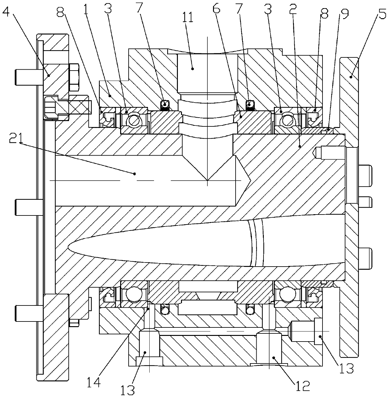
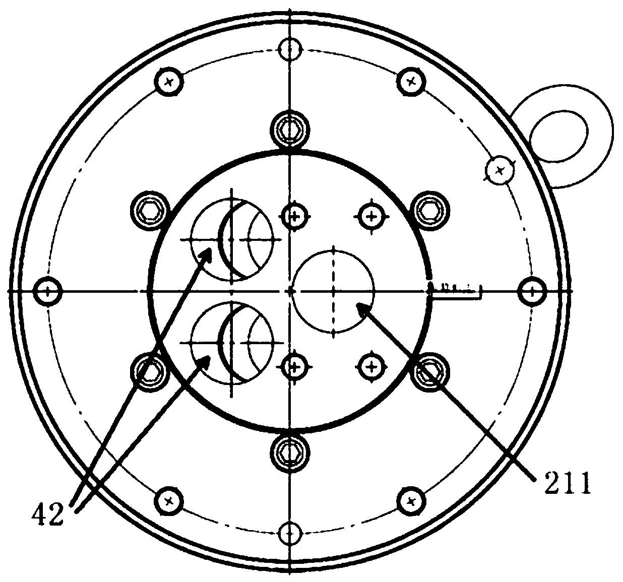
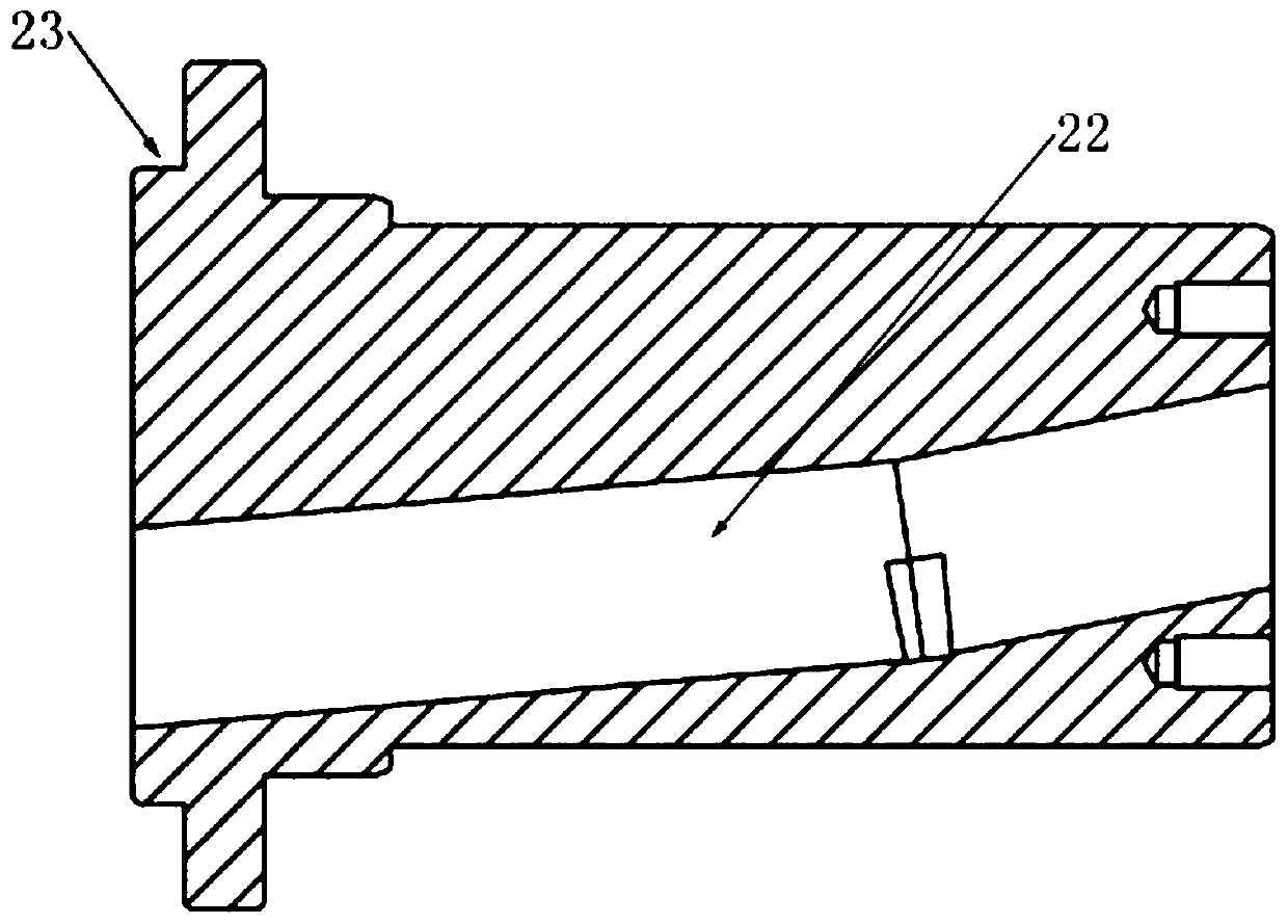
[0016] Such as Figure 1 to Figure 6 As shown, the wind turbine oil slip ring described in this embodiment includes a housing 1, a rotating mandrel 2, a bearing 3, a front flange 4, a rear flange 5, a floating sleeve 6, an elastic sealing ring 7, a rotating shaft seal 8 and a spacer 9, the housing 1 is fixed on the cabin wall of the wind power generator through an external anti-rotation rod, that is, the housing 1 is stationary relative to the cabin, and an oil inlet 11 and an oil drain 12 are processed on its circumferential surface , the rotating mandrel 2 is installed in the housing 1 through two bearings 3 (in order to facilitate the disassembly and assembly of the bearing 3, the two joints of the rotating mandrel 2 and the bearing 3 can also be designed to have different shaft diameters, and the bearings 3 Two kinds of specifications are selected for installation), and a...


PUM


Abstract

The invention discloses an oil slip ring of a wind generating set. The oil slip ring comprises a shell, a rotary mandrel, bearings, a front flange, a rear flange, a floating sleeve, an elastic sealingring, rotary shaft seals and a spacer bush; the shell is of an annular structure; an oil inlet and an oil drainage opening are machined in the circumferential surface of the shell; the rotary mandrelis mounted in the shell through the two bearings; the front flange and the rear flange are installed on the front end surface and rear end surface of the rotary mandrel through screws respectively; the floating sleeve is arranged between the rotary mandrel and the shell and is located between the two bearings; two oil drainage channels are machined in the inner circumferential surface of the shell and are located on the end surfaces of two sides of the floating sleeve respectively; each rotary shaft seal is mounted on one side, away from the floating sleeve, of the corresponding bearing in amatched manner; and the spacer bush is arranged between the rotary mandrel and the rotary shaft seal close to the rear flange. The increased speed of internal leakage of the oil slip ring can be effectively reduced, the overall reliability of the oil slip ring is improved, and the service life of the oil slip ring is prolonged.

Description

technical field [0001] The invention relates to the technical field of wind power generators, in particular to an oil slip ring of a wind power generator. Background technique [0002] The semi-direct drive wind turbine combines the technical advantages of direct drive and doubly-fed units, and has the characteristics of high reliability, high efficiency, and compact structure. , the gear meshing on the primary planet carrier where the rotating part is located and the planetary gear bearing are lubricated by oil injection, and the lubricating oil is input from the oil port of the front cover of the gearbox, and the oil port is connected to the interior of the engine room through the pipeline through the hollow shaft of the transmission chain Therefore, the lubricating oil delivered from the fixed nacelle to the front end of the rotating gearbox must pass through a rotating oil slip ring for transition. At the same time, the oil slip ring also needs to provide an installatio...

Claims


Application Information

Patent Timeline
IPC IPC(8): F03D80/70
CPCF03D80/70Y02E10/72
Inventor 刘震洲黄庆钊石明礼宋昭
Owner GUANGDONG MINGYANG WIND POWER IND GRP CO LTD
Learn More