Low-torque ripple sensorless control method for synchronous reluctance motor

A synchronous reluctance motor and torque ripple technology, applied in torque ripple control, motor generator control, electronic commutation motor control, etc., can solve problems such as noise pollution, high-frequency torque ripple, etc.

Active Publication Date: 2020-04-07
HARBIN INST OF TECH
View PDF2 Cites 6 Cited by
  • Summary
  • Abstract
  • Description
  • Claims
  • Application Information

AI Technical Summary

Problems solved by technology

[0005] Aiming at the problems of high-frequency torque ripple and noise pollution in the direct-axis high-frequency signal injection method used at zero-low speed in the existing synchronous reluctance motor without position sensor control, the present invention provides a synchronous reluctance motor with low torque Pulsation sensorless control method

Method used


Image

  • Low-torque ripple sensorless control method for synchronous reluctance motor
  • Low-torque ripple sensorless control method for synchronous reluctance motor
  • Low-torque ripple sensorless control method for synchronous reluctance motor

Examples


specific Embodiment approach 1

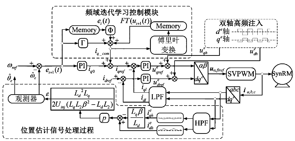
[0067] Specific implementation mode 1. Combination figure 1 As shown, the present invention provides a sensorless control method for low torque ripple of a synchronous reluctance motor, comprising:

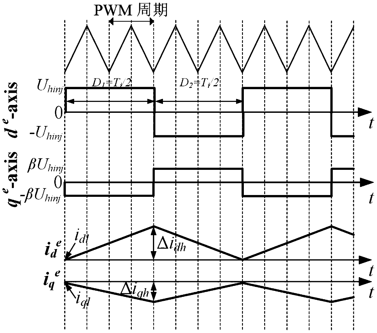
[0068] During the operation of the synchronous reluctance motor, a predetermined high-frequency pulse voltage with the same phase and a fixed amplitude is injected into the dq axis of the synchronous reluctance motor at the same time; the dq axis refers to the rotating coordinate system of the motor, and dq The shaft system includes a d-axis and a q-axis, the d-axis points to the direction where the rotor reluctance is smaller, and the q-axis is perpendicular to the d-axis;

[0069] Extracting the three-phase pulse current in the abc three-phase shaft system of the synchronous reluctance motor, and transforming it into a current signal under the dq shaft system, performing differential calculation on the current signal under the dq shaft system and coupling with coupling parameter...

Embodiment 1

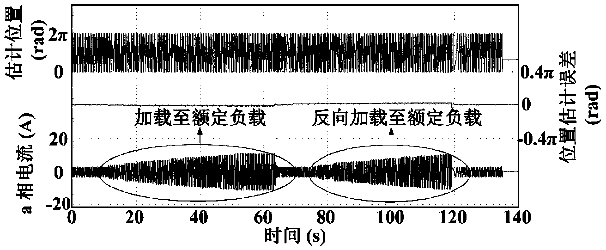
[0111] The verification is carried out on the synchronous reluctance motor towing experimental platform. A 3kW permanent magnet synchronous motor and a 5.5kW permanent magnet synchronous motor are connected through the JN338 torque speed tester, and the two inverters are connected by a common DC bus; the permanent magnet synchronous motor is used as the loading motor, and the synchronous reluctance motor is used as the test motor. The torque speed is monitored in real time by the torque tester. The system is equipped with an encoder to obtain the actual position and compare it with the observed signal; the vector control algorithm is implemented through STM32F103VBARM to control the synchronous reluctance motor; the inverter uses the PM25RLA120IPM power module, and the stator current passes through the PHA20VB15 Hall current sensor Detection; switching frequency 6kHz;

[0112] The main parameters of the synchronous reluctance motor used are: rated voltage 360V, rated current ...


PUM


Abstract

The invention discloses a low-torque ripple sensorless control method for a synchronous reluctance motor, and belongs to the technical field of motor control. The invention aims to solve the problemsof high-frequency torque pulsation and noise pollution of a direct-axis high-frequency signal injection method used at a zero low speed in the position sensorless control of a conventional synchronousreluctance motor. The method comprises the following steps: simultaneously injecting predetermined high-frequency pulse voltages with the same phase and fixed amplitude proportion into a dq shaft system of the synchronous reluctance motor; obtaining a rotor position estimation error based on the extracted three-phase pulse current in the abc three-phase shaft system of the synchronous reluctancemotor; further obtaining a rotor estimation position and a rotor estimation rotating speed which are used for closed-loop control of the motor; and performing calculating to obtain q-axis compensationcurrent, and compensating for the q-axis current of the motor, so the actual rotating speed of the rotor better tracks the given rotating speed of the rotor, and the output torque ripple of the synchronous reluctance motor is reduced. According to the invention, the output torque ripple of the synchronous reluctance motor can be reduced on the basis of realizing sensorless control.

Description

technical field [0001] The invention relates to a low-torque pulsation sensorless control method of a synchronous reluctance motor, belonging to the technical field of motor control. Background technique [0002] Synchronous reluctance motors are widely used in various industrial drive fields because of their high power density, strong robustness, low cost and good dynamic performance. Traditional vector control technology requires motor rotor position information for decoupling control, but the installation of position sensors not only increases the cost, but also reduces the reliability of the system, so position sensorless technology has become one of the main research directions in the field of motor control. [0003] The position sensorless technology is mainly divided into the high-frequency signal injection method used at zero and low speeds and the model method used at medium and high speeds. Because the model method is greatly affected by noise when the speed is lo...

Claims


Application Information

Patent Timeline
Patent Type & Authority Applications(China)
IPC IPC(8): H02P21/05H02P21/18H02P6/18H02P6/10
CPCH02P21/05H02P21/18H02P6/183H02P6/10
Inventor 王高林李成睿张国强赵楠楠徐殿国
Owner HARBIN INST OF TECH
Why Eureka
Try Eureka